
Programmable filters and methods of operation thereof

a programmable filter and filter technology, applied in the field of programmable filters, can solve the problems of insufficient supply of a constant cutoff frequency of a programmable filter prior art solutions

Inactive Publication Date: 2008-05-01
THETA MICROELECTRONICS
View PDF5 Cites 22 Cited by
  • Summary
  • Abstract
  • Description
  • Claims
  • Application Information

AI Technical Summary

Problems solved by technology

Prior art solutions are deficient in providing a constant cutoff frequency of the programmable filter when there is a need to change the input resistance, for example for the purpose of controlling the signal-to-noise ratio.

Method used


Image

  • Programmable filters and methods of operation thereof
  • Programmable filters and methods of operation thereof
  • Programmable filters and methods of operation thereof

Examples


Embodiment Construction

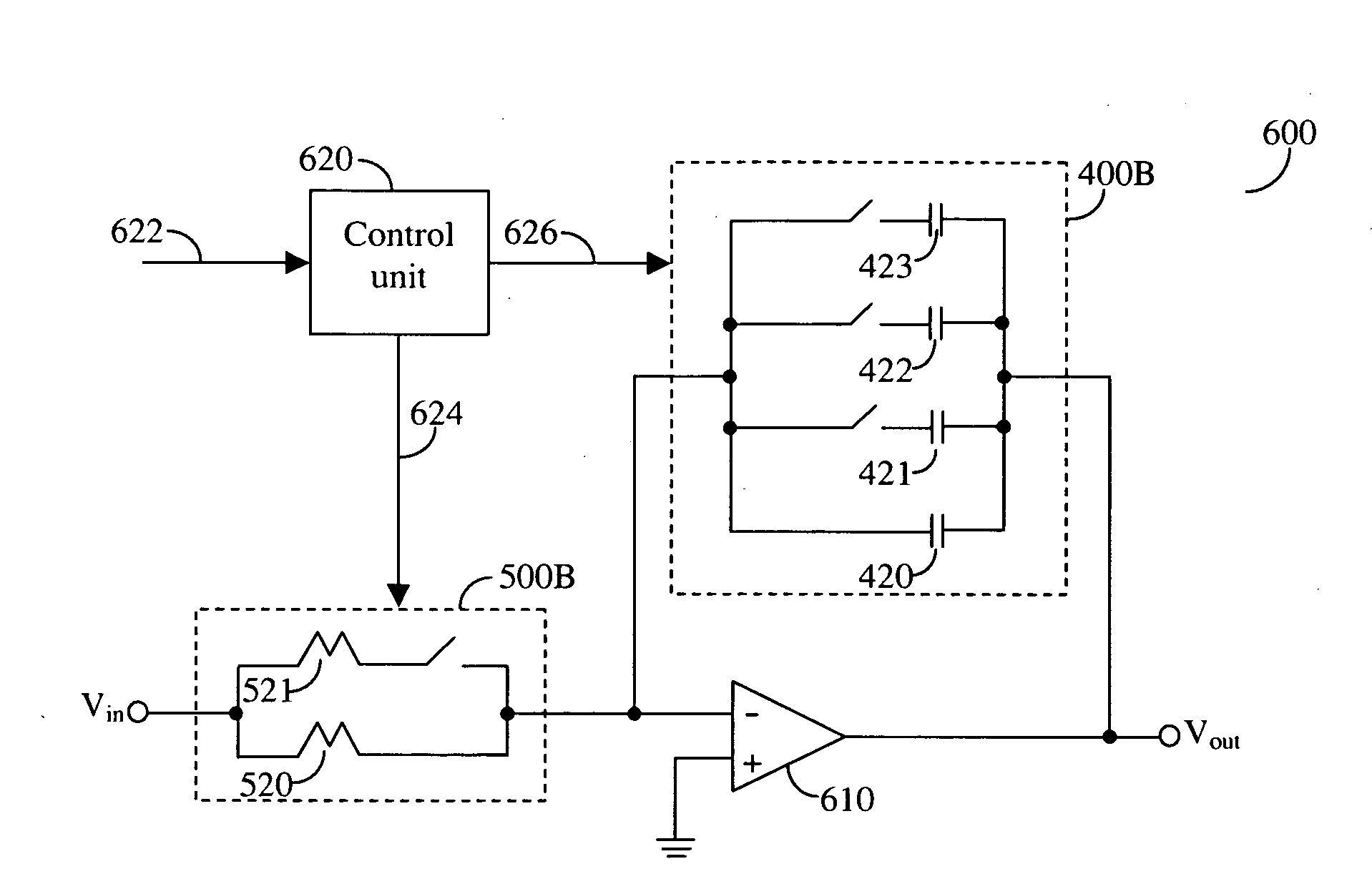
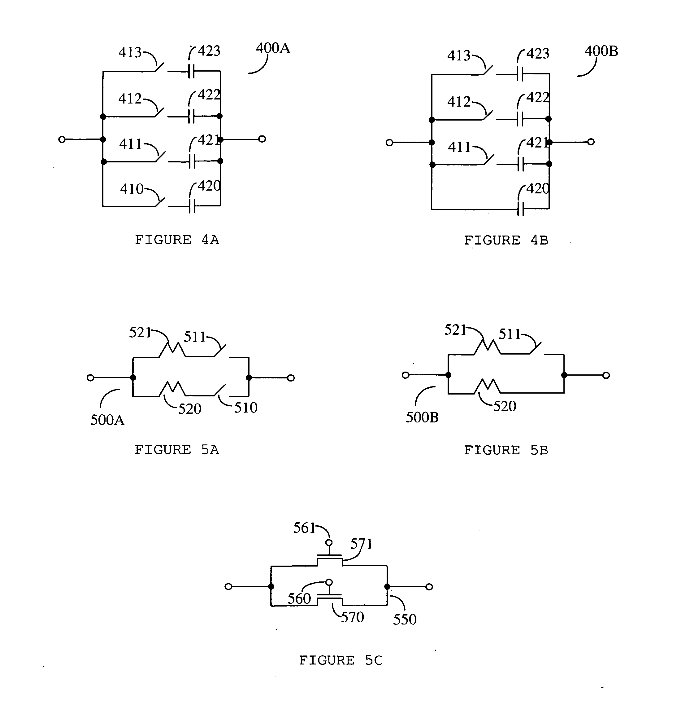
[0022]For the purpose of overcoming the deficiencies of the prior art, a plurality of capacitors are used in a capacitor bank in a negative feedback loop of an amplification means, for example an operational amplifier, each capacitor of the capacitor bank being capable of being either connected or disconnected to the feedback loop by means of a respective switch. In addition, a resistor bank is connected to the inverting input of the amplification means of the filter, each resistor being capable of being connected or disconnected from the circuit input by means of a respective switch. In one embodiment of the disclosed invention all but one of the capacitors and all but one of the resistors are connected to a switch while one capacitor and one resistor are permanently connected. All switches are connected to the virtual ground of the op amp, thus minimizing variations of the gate-source and / or gate-drain voltages, which would otherwise cause a variation in switch resistance and woul...


PUM


Abstract

Programmable filters are used for the purpose of changing the filter cutoff frequency as may be necessary for the operation of a wireless transmitter or receiver. Frequencies may be changed by selecting a desirable value of a capacitor and / or a resistor. The programmable filter controls the frequency according to the disclosed method. Furthermore, in order to reduce the area consumed by the programmable filter a three-dimensional layout is used. In accordance with the disclosed invention it is possible to program the input of the programmable filter to have a higher or lower input resistance as may be required while maintaining the desired programmed cutoff frequency by switching the respective capacitors in a capacitor bank, thereby combining the elements needed for frequency programmability and input impedance level selection.

Description

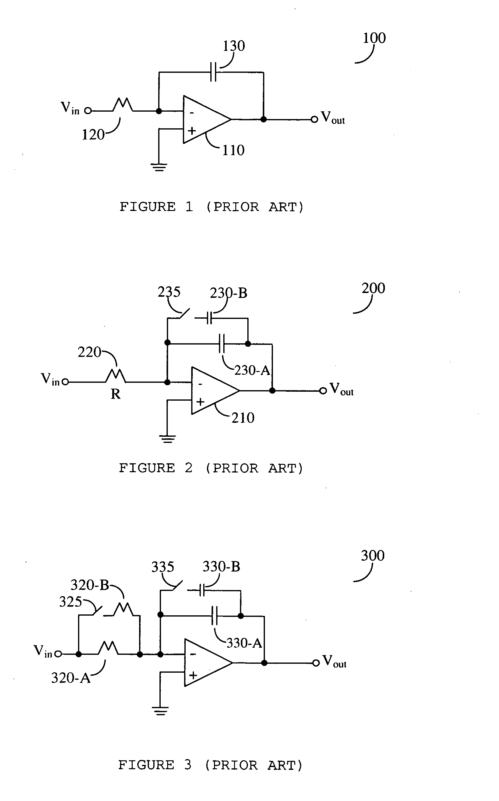
BACKGROUND OF THE INVENTION[0001]1. Field of the Invention[0002]The present invention relates generally to programmable filters, and more specifically relates to programmable cut-off or center frequency filters.[0003]2. Prior Art[0004]The use of operational amplifiers for the purpose of creating a variety of low-pass, high-pass and band-pass filters is well known in the art. Referring to FIG. 1, there is shown a simple integrator 100, also known in the art as the Miller integrator. The integrator is comprised of an operational amplifier 110, a resistor 120 connected to the inverting input of operational amplifier 110, and a capacitor 130 providing a feedback path from the output to the inverting input of operational amplifier 110. The characteristics of integrator 100, i.e., the specific corner frequency of integrator 100, depend on the values of resistor 120 and capacitor 130.[0005]For the purpose of providing a plurality of corner frequencies, it is customary to connect one or mor...

Claims


Application Information

Patent Timeline
Patent Type & Authority Applications(United States)
IPC IPC(8): H03B1/00
CPCH03H11/1291H03H2210/036H03H2210/028H03H2210/025
Inventor PAPANANOS, YANNISTSIVIDIS, YANNIS
Owner THETA MICROELECTRONICS
Learn More