QoS ROUTING METHOD AND QoS ROUTING APPARATUS

a routing method and routing technology, applied in the field of qos routing technology, can solve the problems of lowering measurement accuracy, affecting the communication quality of respective links, and affecting so as to achieve the effect of preventing the measurement accuracy of the communication quality of the respective link, lowering measurement accuracy, and high measurement accuracy

Active Publication Date: 2008-05-01
NEC CORP
View PDF7 Cites 130 Cited by
  • Summary
  • Abstract
  • Description
  • Claims
  • Application Information

AI Technical Summary

Benefits of technology

[0013] According to the present invention, when QoS routing is carried out, a control can be dynamically carried out to guide a specific flow to a link with the lower measurement accuracy. With this operation, the measurement accuracy of the communication qualities of the resp...

Problems solved by technology

However, the methods of obtaining quality information by the measurement described above have the following problems.
A first problem resides in that when the active measurement is used as a measurement method, a measurement flow applies an extra load to a network.
As a result, the transmission of an ordinary packet fails.
A second ...

Method used


Image

  • QoS ROUTING METHOD AND QoS ROUTING APPARATUS
  • QoS ROUTING METHOD AND QoS ROUTING APPARATUS
  • QoS ROUTING METHOD AND QoS ROUTING APPARATUS

Examples


first embodiment

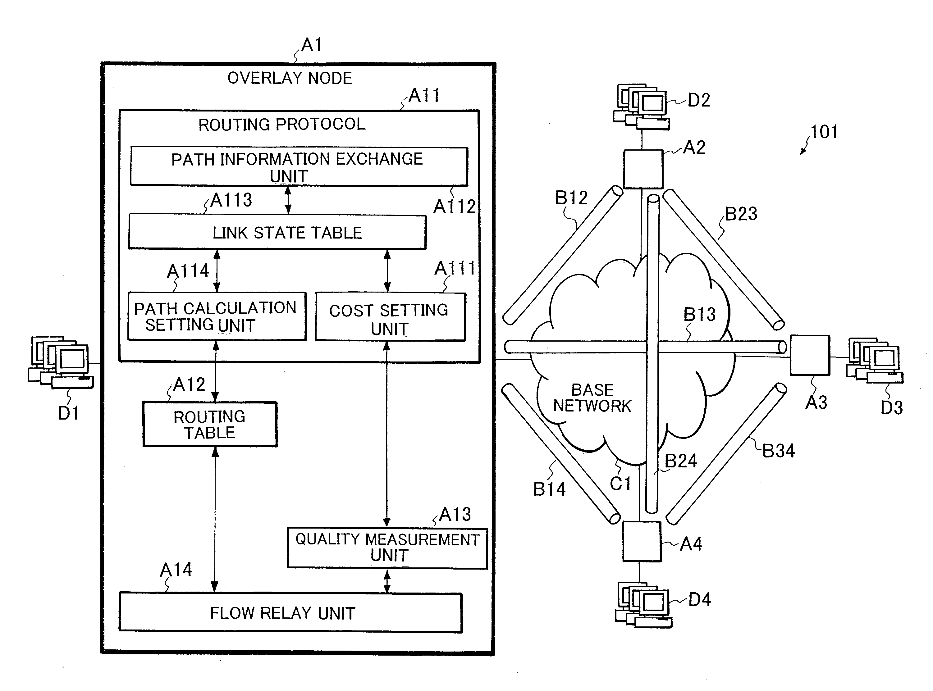
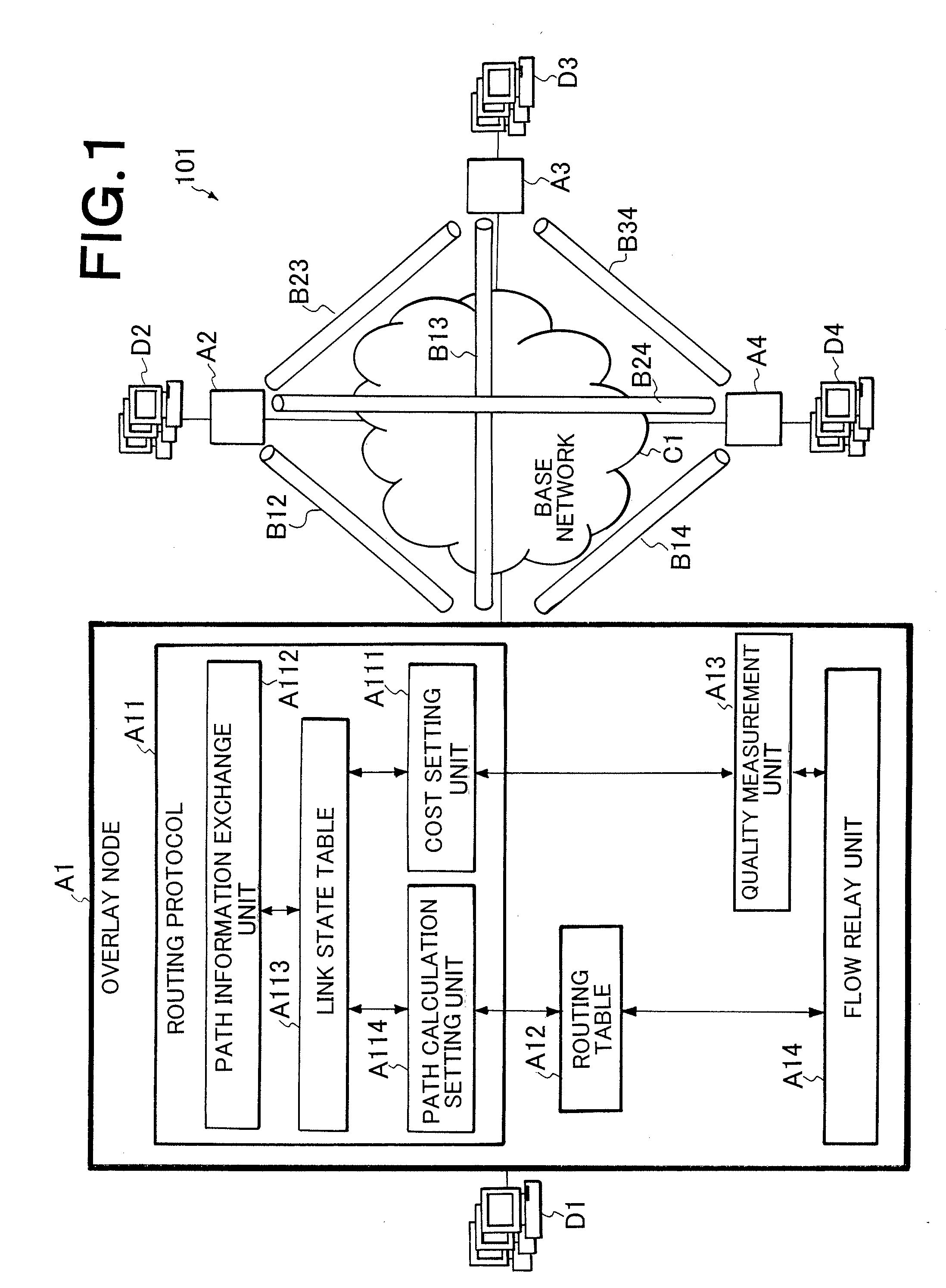
[0023]FIG. 1 shows an arrangement of the present invention. A system 101 of the embodiment is composed of overlay nodes A1-A4, links B12-B34, a base network C1, and terminal groups D1-D4. The overlay nodes A1-A4 are connected to the physical base network C1 and form an overlay network by links B12-B34 which are logical transmission paths set on the base network C1.

[0024] The user's terminal groups D1-D4 are connected to the overlay nodes A1-A4. The terminal groups D1-D4 denote an assembly of equipment such as a client, a server, and the like under the control of the overlay nodes A1-A4, respectively and carry out a communication with each other.

[0025] Since each of the overlay nodes A1-A4 has the same arrangement, the arrangement will be explained below as to the overlay node A1 as an example. As shown in FIG. 1, the overlay node A1 includes a routing protocol A11, a routing table A12, a quality measurement unit A13, and a flow relay unit A14.

[0026] The routing protocol A11 has a ...

third embodiment

[0088] described above, since the flow division / relay unit A17 has a function for dividing one measurement flow into a plurality of flows and flows them to a plurality of path, a larger number of links can be measured by a smaller number of measurement flows, thereby measurement can be carried out effectively. Further, since the measurement flow is flown to a plurality of paths and links at the same time, there is an advantage in that the correlation between the links can be easily measured.

[0089] In the embodiment, a destination port number is used as the identifier (FIG. 4) of the measurement flow. However, when the present invention is carried out, a data pattern (signature) included in a received packet, for example, may be used the identifier of the measurement flow in addition to the destination port number. In this case, when a pattern which is detected from a received packet agrees with a previously defined pattern, it is determined that the packet corresponds to the measur...


PUM


Abstract

A QoS routing apparatus as a node of a logical network to transmit data communicated between user's terminals comprises a relay unit discriminating whether or not flows of received data are measurement flows and transmitting said received data, a quality measurement unit measuring communication quality of links connected the own apparatus using the measurement flows, a quality accuracy setting unit determining measurement accuracy of the communication qualities of the respective links and a path setting unit prescribing transmission amounts of the measurement flows to the respective links. When the path setting unit prescribes the transmission amounts of the measurement flows, it applies a higher rate to a link which has been determined a lower measurement accuracy.

Description

[0001] This application is based upon and claims the benefit of priority from Japanese patent application No. 2006-294458, filed on Oct. 30, 2006, the disclosure of which is incorporated herein in its entirety by reference. BACKGROUND OF THE INVENTION [0002] 1. Field of the Invention [0003] The present invention relates to a QoS routing technology for controlling communication quality of a network, and, more particularly, to a QoS routing technology for a logical network which can select an appropriate path from a plurality of candidate paths such as an overlay network and MPLS (Multi Protocol Label Switching) network. [0004] 2. Description of the Related Art [0005] A QoS routing technology realizes a path selection and a path control based on a state of a network to optimize the rate of usage of a network resource and to improve communication quality. For example, Japanese Patent Application Laid-Open Publication No. 2006-109454 and Japanese National-Publication-of-Translated-Versi...

Claims


Application Information

Patent Timeline
IPC IPC(8): H04L12/56H04L45/122
CPCH04L45/12H04L45/123H04L45/20H04L45/26H04L45/50H04L45/64H04L47/24H04L47/2425
Inventor FUJITA, NORIHITOJIBIKI, MASAHIRO
Owner NEC CORP
Why Eureka
Try Eureka