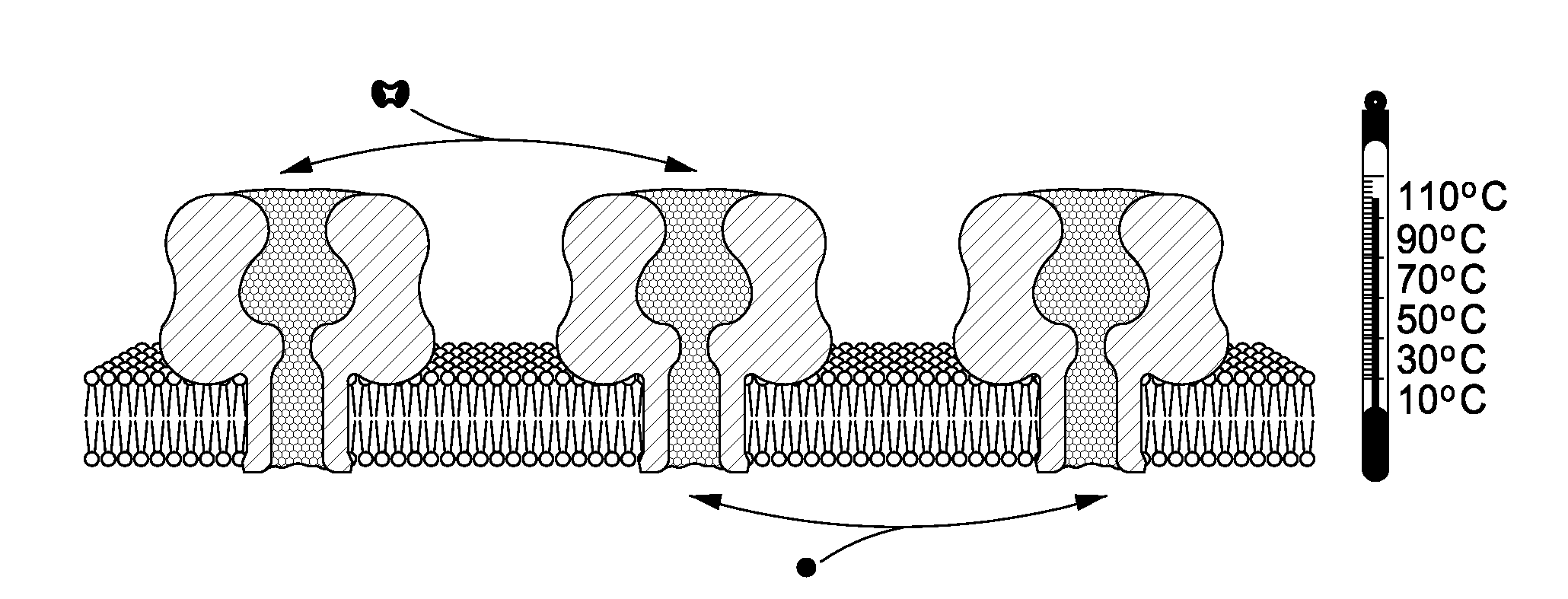
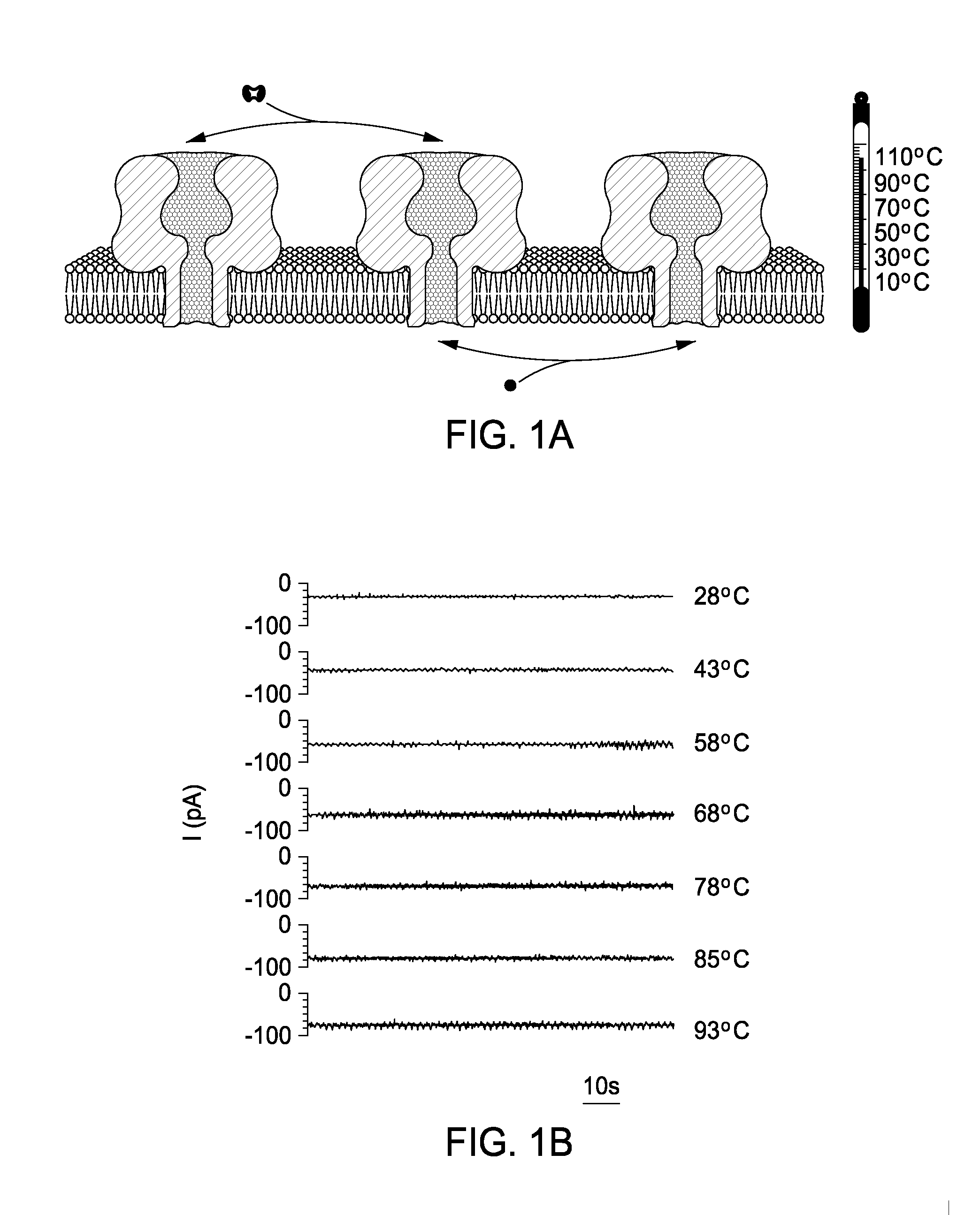
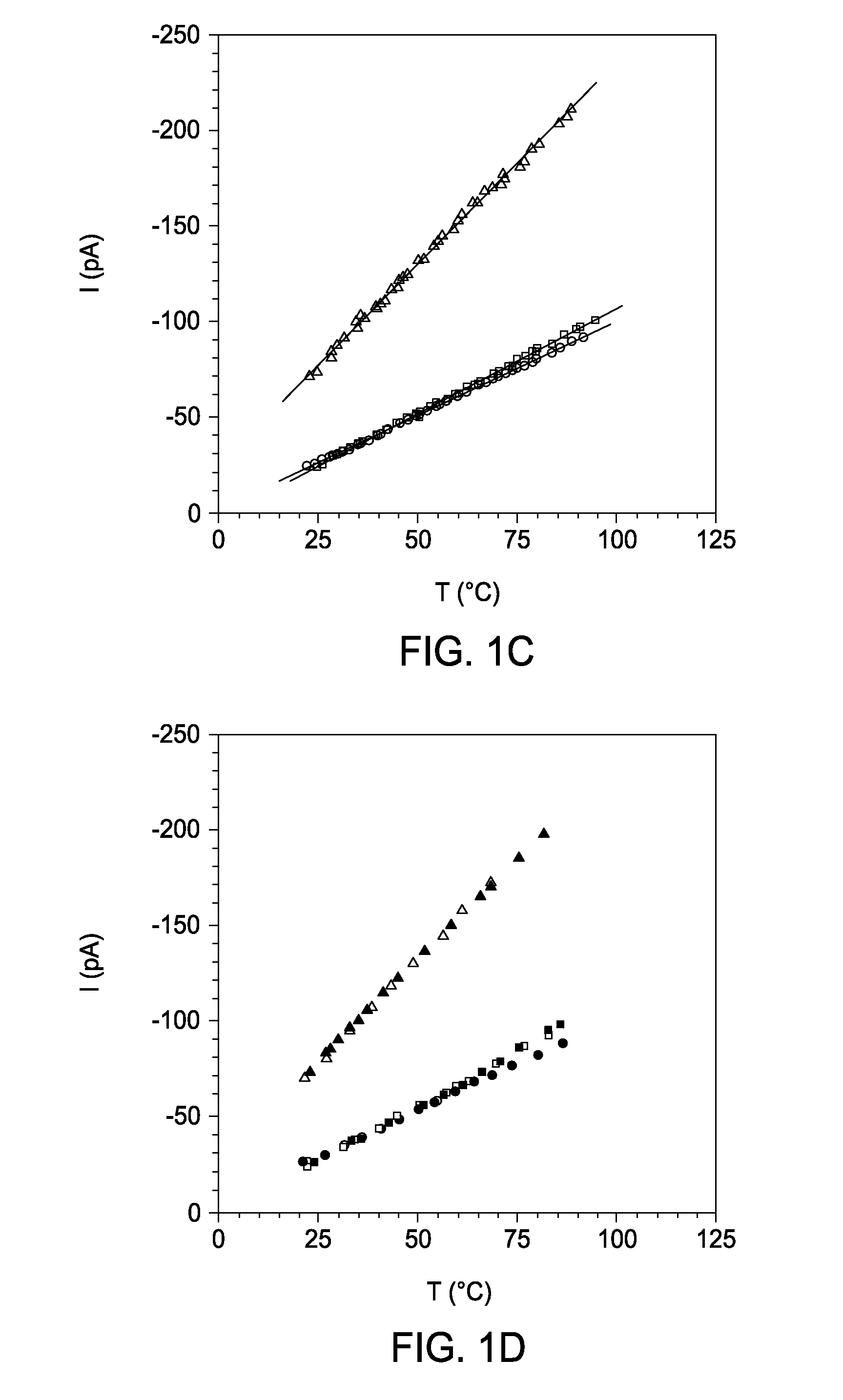
High temperature ion channels and pores
a technology of ion channels and pores, applied in the field of ion channels, can solve the problems of few measurements of membrane protein activity at temperatures above, none of them for ion channels and pores, etc., and achieve the effect of facilitating any stochastic sensing and easily substituting protein pores
- Summary
- Abstract
- Description
- Claims
- Application Information
AI Technical Summary
Benefits of technology
Problems solved by technology
Method used
Image
Examples
example 1
[0064]Pore formation. Wild-type αHL pores were formed by treating monomeric αHL, purified from Staphylococcus aureus, with deoxycholate (S. Bhakdi, R. Füssle, J. Tranum-Jensen, Proc. Natl. Acad. Sci. USA, 78, 5475-5479 (1981)). Heptamers were isolated from SDS-polyacrylamide gels (O. Braha, B. Walker, S. Cheley, J. J. Kasianowicz, L. Song, J. E. Gouaux, H. Bayley, Chem. Biol. 4, 497-505 (1997). The mutant αHL M113N, which was made in a WT-αHL background (L.-Q. Gu, S. Cheley, H. Bayley, Science 291, 636-640 (2001)), was synthesized in vitro by coupled transcription and translation (IVTT) and assembled into homoheptamers by the inclusion of rabbit red cell membranes (rRBCM) during synthesis (S. Cheley, O. Braha, X. Lu, S. Conlan, H. Bayley, Protein Sci. 8, 1257-1267 (1999). The heptamers were purified by SDS-polyacrylamide gel electrophoresis and stored in aliquots at −80° C. Leukocidin pores were prepared by co-translation of the F and S subunits in the presence of rRBCM and purified...
example 2
[0065]Apparatus. One example of the detector 10 used in conjunction with the studies described herein includes a specially designed Teflon block 12, a stainless steel stand 14, and a Peltier device 16 (FIG. 4, side, top and bottom views). The block 12 includes two chambers (18A, 18B), designated cis and trans (or alternatively, first and second shambers). The planar lipid bilayer is formed across a 100-150 μm-diameter orifice in a 25 μm thick Teflon film 20 that separates the two chambers 18A, 18B. The bigger cylindrical holes (22A, 22B) (diameter=5 mm), which are connected to the main chambers 18A, 18B, are used for holding the electrodes (not depicted). The smaller holes (24A-D) (diameter=1.5 mm) are used for holding a thermocouple (not depicted), the tip of which is exposed to an electrolyte and therefore accurately monitors the temperature in the main chamber. The two chambers 18A, 18B are clamped tightly together in a stand 14 made of, e.g., stainless steel. The bottoms of the ...
example 3
[0066]Temperature Control. The temperature in the chamber 12 (FIG. 4) was controlled by using a Peltier device 16 (FerroTec, TZ21084-01). The top part of the chamber was built from Teflon, but the bottom was formed from a thin piece of borosilicate glass 26 (0.16 mm thick; Lab-Tek, Part No. 155361), so that heat transfer between the solution in the chamber 12 and the surface of the Peltier device 16 element was efficient. The temperature in the chamber 12 was controlled by varying the current through the Peltier device 16 with a DC power supply (TENMA, 72-6153). To reverse the temperature ramp, the polarity of the DC power was switched. Cooling was aided by the steel stand 14 underlying the glass bottom. The temperature of the electrolyte in the chamber 12 was recorded with a calibrated thermocouple. The system rapidly and accurately controls the solution temperature: heating rate 35° C. min−1; cooling rate 10° C. min−1 ; temperature: ±0.2°e. It can be used over a broad temperature ...
PUM
| Property | Measurement | Unit |
|---|---|---|
| temperature | aaaaa | aaaaa |
| temperature | aaaaa | aaaaa |
| temperature | aaaaa | aaaaa |
Abstract
Description
Claims
Application Information
 - R&D
- Intellectual Property
- Life Sciences
- Materials
- Tech Scout
- Unparalleled Data Quality
- Higher Quality Content
- 60% Fewer Hallucinations
Browse by: Latest US Patents, China's latest patents, Technical Efficacy Thesaurus, Application Domain, Technology Topic, Popular Technical Reports.
© 2025 PatSnap. All rights reserved.Legal|Privacy policy|Modern Slavery Act Transparency Statement|Sitemap|About US| Contact US: help@patsnap.com


