

Liquid recovery member, substrate holding member, exposure apparatus and device manufacturing method
a technology of substrate holding member and liquid recovery member, which is applied in the direction of photomechanical treatment, printing, instruments, etc., can solve the problems of difficult liquid recovery and achieve the effect of desired performan
- Summary
- Abstract
- Description
- Claims
- Application Information
AI Technical Summary
Benefits of technology
Problems solved by technology
Method used
Image

Examples
first embodiment
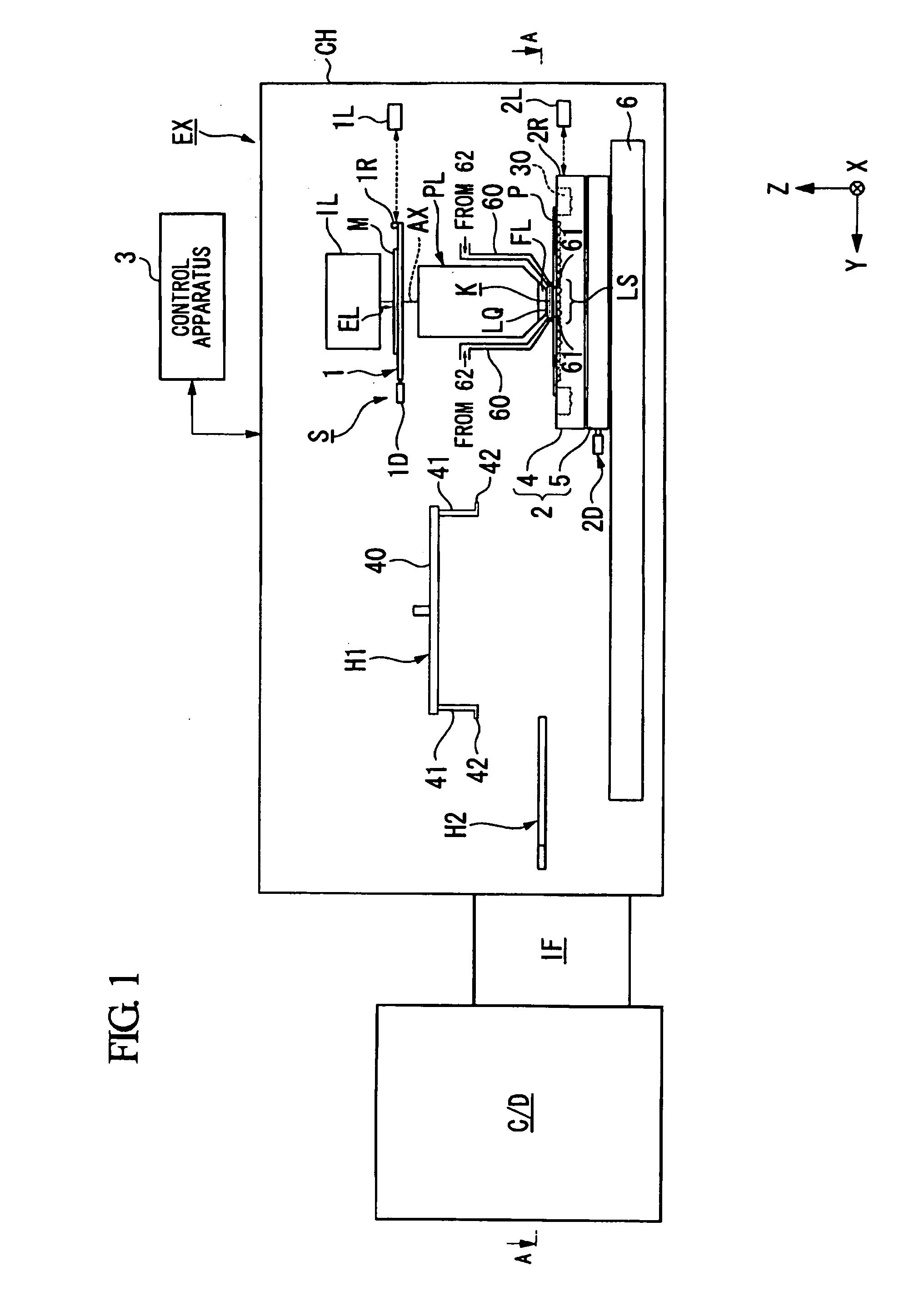
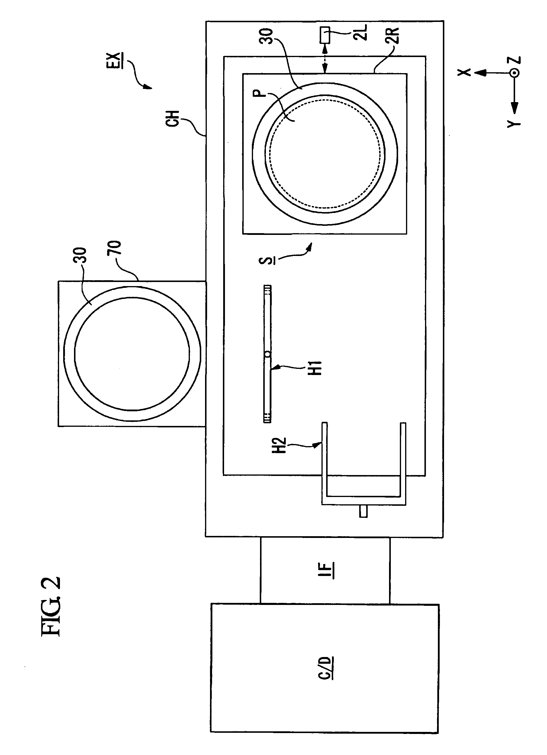
[0044]A first embodiment will be explained. FIG. 1 is a side view showing a schematic configuration of an exposure apparatus EX according to a first embodiment. FIG. 2 is a plan view showing a schematic configuration of the exposure apparatus EX according to the first embodiment, which corresponds to a cross-sectional view taken along the A-A arrow of FIG. 1.
[0045]In FIG. 1 and FIG. 2, the exposure apparatus EX includes: an exposure apparatus body S for irradiating an exposure light EL onto a substrate P to exposure process the substrate P; and a control apparatus 3 for controlling operation of the whole exposure apparatus EX.
[0046]The exposure apparatus body S includes: a mask stage 1 capable of holding and moving a mask M with a pattern; a substrate stage 2 capable of holding and moving the substrate P onto which the exposure light EL is irradiated; an illumination system IL for illuminating the mask M held on the mask stage 1 with the exposure light EL; and a projection optical s...
second embodiment
[0155]Next is a description of a second embodiment. In the following description, components the same as or similar to those of the aforementioned first embodiment are denoted by the same reference symbols, and description thereof is simplified or omitted.
[0156]FIG. 18 is an enlarged view of a part of a side cross-sectional view showing a vicinity of the substrate stage 2 according to the second embodiment. In the aforementioned first embodiment, the liquid recovery member 30 is held in the second holding portion 9 so that a part of the opening portion 31 faces the bottom surface of the substrate P held on the first holding portion 8. However, a characteristic point of the present embodiment lies in that the opening portion 31 does not face the bottom surface of the substrate P.
[0157]In the present embodiment, the holder member 4 holds the liquid recovery member 30 in the second holding portion 9 so that at least a part of the liquid recovery member 30 and the overhang region PH of ...
third embodiment
[0161]Next is a description of a third embodiment. In the following description, components the same as or similar to those of the abovementioned embodiments are denoted by the same reference symbols, and description thereof is simplified or omitted.
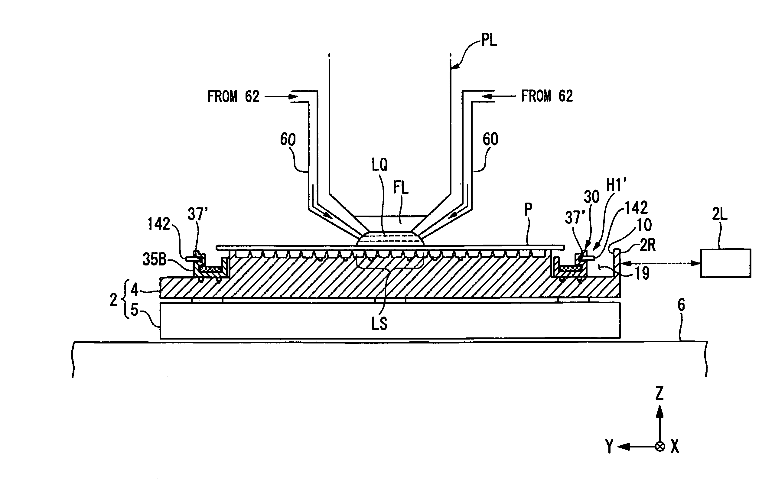
[0162]FIG. 19 is an enlarged view of part of a side cross-sectional view showing a vicinity of a substrate stage 2 according to the third embodiment. As shown in FIG. 19, the liquid recovery member 30 has a recess portion 37′ that is supported by the first transfer system H1. In the present embodiment, the recess portion 37′ is an annular groove portion that is formed in the outer side surface 35B of the second side plate 35 of the liquid recovery member 30. At a lower end of each of arm members 41′ of the first transfer system H1, a protrusion portion 42′ is formed that is capable of being arranged inside the recess portion 37 of the liquid recovery member 30. The protrusion portions 42′ protrude, substantially in parallel with the supp...
PUM
| Property | Measurement | Unit |
|---|---|---|
| wavelength | aaaaa | aaaaa |
| wavelength | aaaaa | aaaaa |
| wavelength | aaaaa | aaaaa |
Abstract
Description
Claims
Application Information