Travel control system for vehicle

Inactive Publication Date: 2008-05-08
HONDA MOTOR CO LTD
View PDF8 Cites 20 Cited by
  • Summary
  • Abstract
  • Description
  • Claims
  • Application Information

AI Technical Summary

Benefits of technology

[0009] The present invention has been attained in view of the above circumstances. An aspect of the present invention is to p

Problems solved by technology

Accordingly, in the system disclosed by JP '100, the movement of the subject vehicle becomes jerky when starting the following-travel control at the t

Method used


Image

  • Travel control system for vehicle
  • Travel control system for vehicle
  • Travel control system for vehicle

Examples


Embodiment Construction

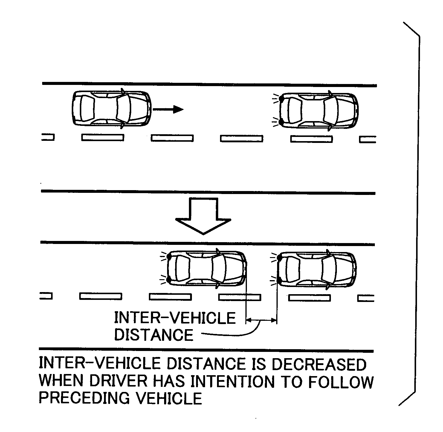
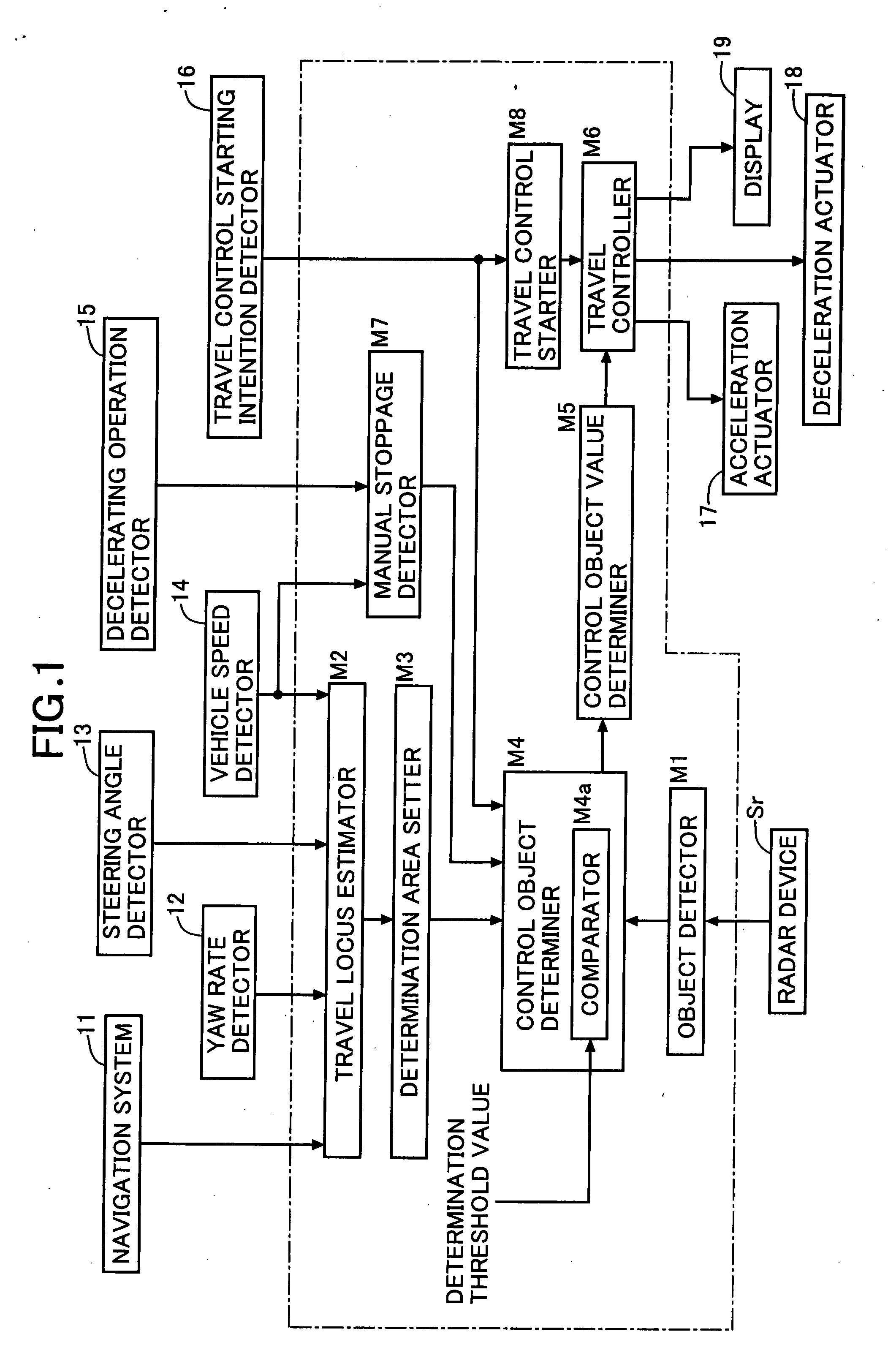
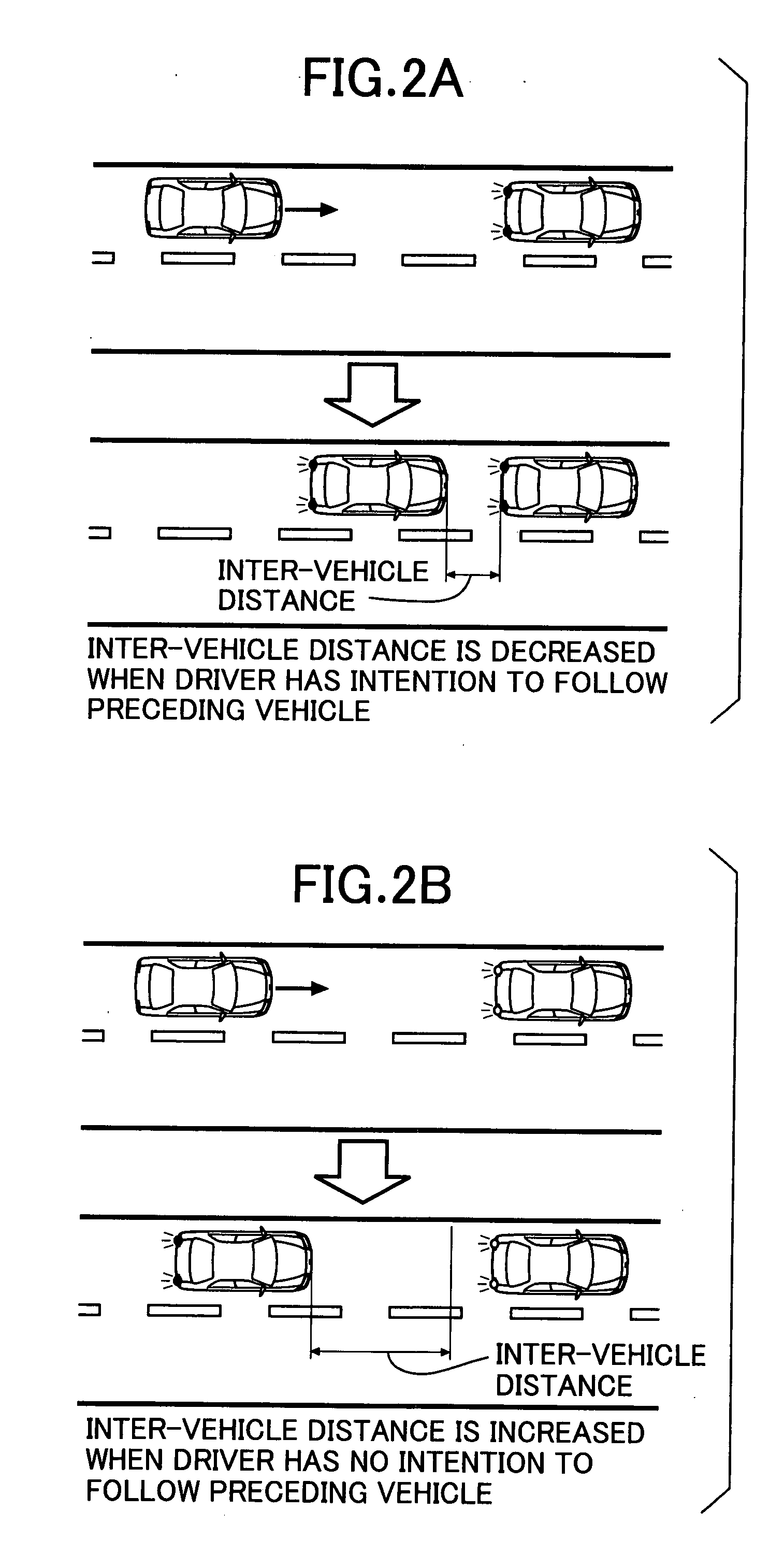
[0026] Referring to FIG. 1, a block diagram of a following-travel control system is illustrated. The following-travel control system causes a subject vehicle to travel at a predetermined inter-vehicle distance from a preceding vehicle traveling ahead of the subject vehicle while primarily in a lower vehicle speed region. When the preceding vehicle decelerates and stops, the following-travel control system correspondingly causes the subject vehicle to decelerate and stop. The following-travel control system includes an object detector M1, a travel locus estimator M2, a determination-area setter M3, a control object determiner M4, a comparator M4a, a control target value determiner M5, a travel controller M6, a manual stoppage detector M7, and a travel control starter M8.

[0027] A radar device Sr, such as a laser radar device or a millimeter wave radar device, is connected to the object detector M1. A navigation system 11, a yaw rate detector 12, a steering-angle detector 13, and a ve...


PUM


Abstract

A travel controller which controls the travel of a subject vehicle based on a distance to and a relative speed with respect to a control object determined by a control object determiner. If stoppage of the subject vehicle by a decelerating operation of a driver is detected by a manual stoppage detector and a comparator determines that a distance to the object in or on a travel locus is equal to or larger than a determination threshold value, the comparator excludes the object from being considered as a control object.

Description

BACKGROUND OF THE INVENTION [0001] 1. Field of the Invention [0002] The present invention relates to a travel control system for a vehicle which causes the vehicle to follow a preceding vehicle at a predetermined inter-vehicle distance in a low vehicle speed region. [0003] 2. Description of the Related Art Japanese Patent Application Laid-open No. 2002-319100 (JP '100) discloses a travel locus estimating system which estimates a future travel locus of a subject vehicle based on a yaw rate and a speed of the vehicle. In the disclosed system, to compensate for a decrease in the accuracy of estimating the travel locus due to a decrease in the accuracy of detecting the yaw rate at a lower vehicle speed, such as when the vehicle is being started, an estimated travel locus before stoppage of the subject vehicle is stored. As such, when the subject vehicle is started after the stoppage, a following-travel control of the subject vehicle is performed using the stored estimated travel locus, ...

Claims


Application Information

Patent Timeline
IPC IPC(8): B60W30/08B60R21/00B60W30/00B60W30/16G01S13/93G08G1/16
CPCB60W30/08B60W2420/52B60W30/17
Inventor SAWAMOTO, KIICHIRO
Owner HONDA MOTOR CO LTD
Why Eureka
Try Eureka