
Wireless Communication System, Wireless Communication Apparatus, Wireless Communication Method, and Computer Program

a wireless communication and wireless communication technology, applied in the field of wireless communication systems, wireless communication apparatuses, wireless communication methods, computer programs, can solve the problems of not being able to describe the actual (high-speed) transmission rate, communication is susceptible to parity errors, and the chance of recovery might be missed, so as to maintain compatibility and be robust against parity errors

Active Publication Date: 2008-05-08
SONY CORP
View PDF9 Cites 56 Cited by
  • Summary
  • Abstract
  • Description
  • Claims
  • Application Information

AI Technical Summary

Benefits of technology

[0025]There also exists a demand for a favorable wireless communication system, wireless communication apparatus, wireless communication method, and computer program that are robust against parity errors that occur in SIGNAL fields representing information such as a transmission rate, a data length, etc. in preambles.
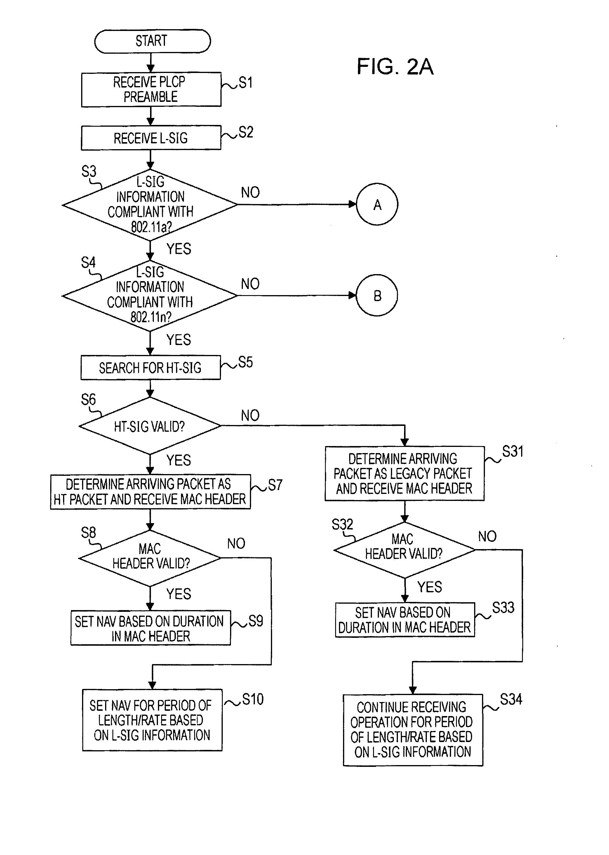
[0031]Thus, in the wireless communication system, the HT terminal as the second communication station includes detecting means for detecting whether the content of the L-SIG (i.e., the first signal field according to the first communication protocol) is complaint. When information included in the L-SIG is not compliant, even when no parity error is detected, the information read from the L-SIG is considered as invalid and is discarded. This serves to improve the accuracy of error detection in the L-SIG.
[0047]Furthermore, even when a valid second signal field is received, when a valid MAC frame is not received subsequently, the communication controlling means may set a transmission waiting period on the basis of the value obtained by dividing the value of the length field by the value of the rate field in the first signal field. In this case, a wireless communication apparatus that operates as the second communication station sets a NAV for the transmission waiting period determined by dividing the value of the length field by the value of the rate field on the basis of information in the L-SIG instead of the duration information in the MAC header, and refrains from transmission during the transmission waiting period. Since the possibility of errors in the L-SIG field is reduced, the transmission waiting period can be determined more appropriately.
[0050]According to these embodiments of the present invention, it is possible to provide a favorable wireless communication system, wireless communication apparatus, wireless communication method, and computer program that allow communications appropriately according to the IEEE 802.11n while maintaining compatibility with the IEEE 802.11a / g.
[0051]Furthermore, according to these embodiments of the present invention, it is possible to provide a favorable wireless communication system, wireless communication apparatus, wireless communication method, and computer program that allow executing a packet exchanging sequence correctly on the basis of information included in preambles.
[0052]Furthermore, according to these embodiments of the present invention, it is possible to provide a favorable wireless communication system, wireless communication apparatus, wireless communication method, and computer program that are robust against parity errors that occur in SIGNAL fields representing information such as a transmission rate, a data length, etc. in preambles.

Problems solved by technology

Thus, it is not allowed to describe the actual (high-speed) transmission rate, which is not supported in the legacy mode.
In this case, errors that occur at an even number of bits are not detected (refer to FIG. 9), so that communications are susceptible to parity errors.
However, such a chance of recovery might be missed when errors that occur at an even number of bits are not detected.

Method used


Image

  • Wireless Communication System, Wireless Communication Apparatus, Wireless Communication Method, and Computer Program
  • Wireless Communication System, Wireless Communication Apparatus, Wireless Communication Method, and Computer Program
  • Wireless Communication System, Wireless Communication Apparatus, Wireless Communication Method, and Computer Program

Examples


Embodiment Construction

[0067]Now, embodiments of the present invention will be described in detail with reference to the drawings.

[0068]The present invention relates to communications over wireless transmission paths in a network including a plurality of communication stations. Furthermore, the present invention assumes store-and-forward traffic in which information is transferred in packets. As an example, in a communication environment assumed in an embodiment of the present invention, legacy terminals compliant with the IEEE 802.11a / g and HT terminals compliant with the IEEE 802.11n, which is a high-throughput (HT) version that uses the same band, are allowed to operate.

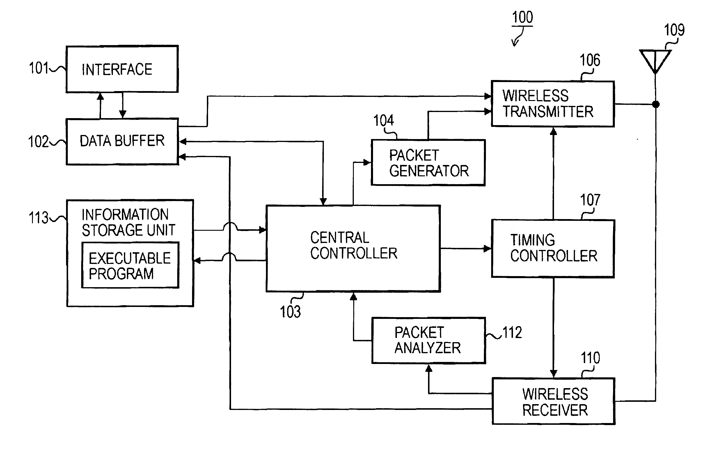
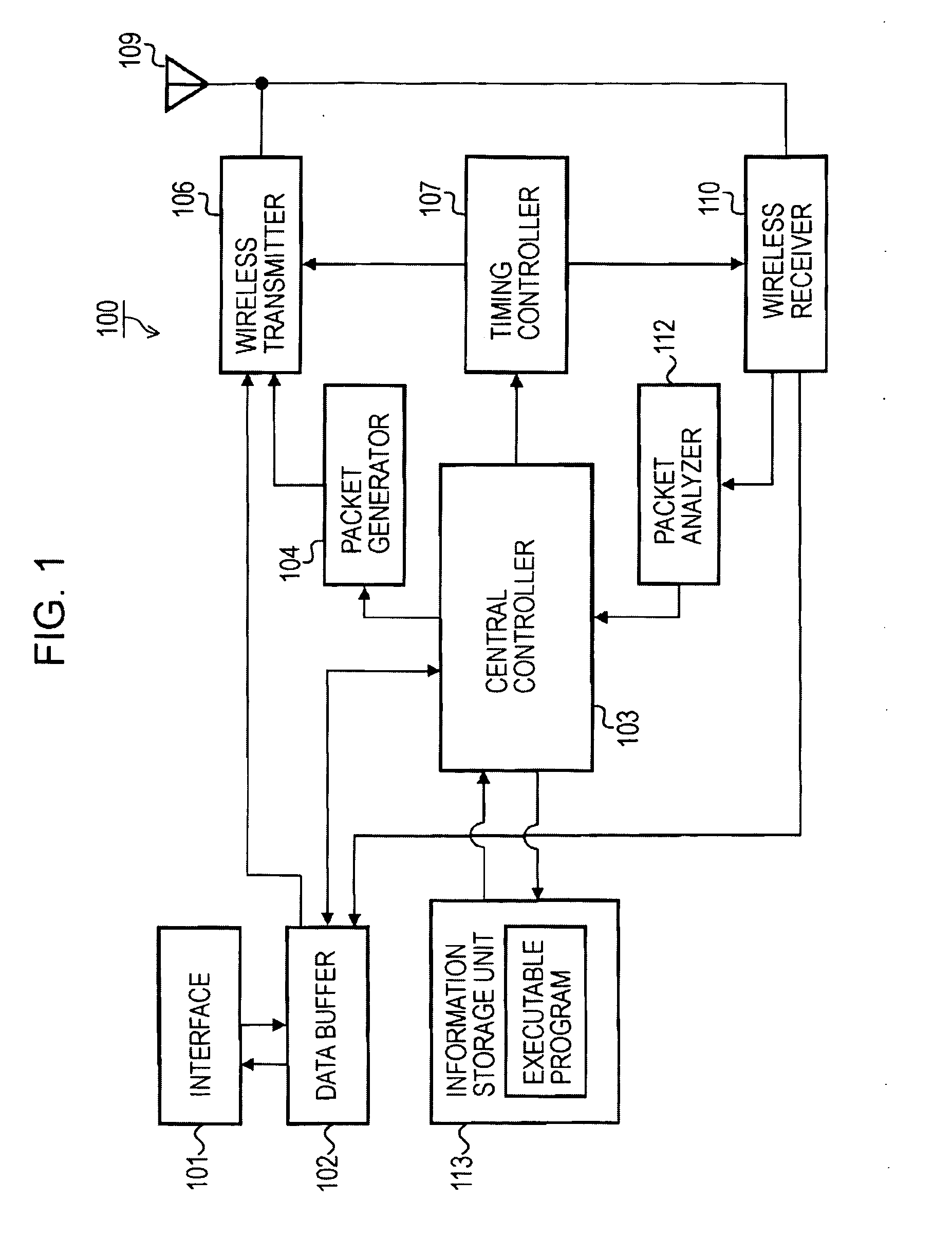
[0069]FIG. 1 schematically shows the functional configuration of a wireless communication apparatus that operates as a communication terminal in a wireless network in an embodiment of the present invention. Referring to FIG. 1, a wireless communication apparatus 100 includes an interface 101, a data buffer 102, a central controller 103,...


PUM


Abstract

A wireless communication system includes a first communication station configured to operate according to a first communication protocol, and a second communication station capable of operating according to both the first communication protocol and a second communication protocol. When the second communication station transmits a packet according to the second communication protocol, at least a first signal field compliant with the first communication protocol and a second signal field compliant with the second communication protocol are attached to a header of the packet, and the first signal field includes a parity bit. When the second communication station receives a packet from another communication station, the second communication station performs a parity check on the first signal field of the packet, and when no parity error is detected, the second communication station further checks whether content of the first signal field is compliant with the first communication protocol.

Description

CROSS REFERENCES TO RELATED APPLICATIONS[0001]The present invention contains subject matter related to Japanese Patent Application JP 2006-176094 filed in the Japanese Patent Office on Jun. 27, 2006, the entire contents of which are incorporated herein by reference.BACKGROUND OF THE INVENTION[0002]1. Field of the Invention[0003]The present invention relates to wireless communication systems, wireless communication apparatuses, wireless communication methods, and computer programs for carrying out communications mutually among a plurality of wireless stations in a wireless local area network (LAN), a wireless personal area network (PAN), or the like. For example, the present invention relates to a wireless communication system, a wireless communication apparatus, a wireless communication method, and a computer program for carrying out communications according to the IEEE 802.11n while maintaining compatibility with the IEEE 802.11a / g.[0004]More specifically, the present invention rel...

Claims


Application Information

Patent Timeline
IPC IPC(8): G06F11/10H04W28/04H04W28/06H04W72/04H04W84/12H04W88/06
CPCH04L69/08H04L1/0063
Inventor MORIOKA, YUICHISAKODA, KAZUYUKI
Owner SONY CORP
Learn More