Deaeration Device and Method of Use

a technology of degasification device and degasification method, which is applied in the direction of liquid degasification, lighting and heating apparatus, separation processes, etc., can solve the problem of low level of pumping loss

Inactive Publication Date: 2008-05-15
SHEPPARD MULLIN RICHTER & HAMPTON
View PDF6 Cites 20 Cited by
  • Summary
  • Abstract
  • Description
  • Claims
  • Application Information

AI Technical Summary

Benefits of technology

[0003]An aspect of the present invention involves a deaeration device that utilizes the principle that bubbles will more readily escape from a slow moving fluid flow or stationary pool rather than a fast moving fluid flow, and that in a closed flow loop, the same fluid will circulate around the loop multiple times in a relatively short period of time. The deaeration device includes a hollow tube with two cutouts, integrated into a reservoir, where the tube is submerged in the reservoir fluid. The first cutout is at an angle, and has an attached plate that effectively “skims” or “strips” off part of the fluid flow from the top of the tube. This top layer of the fluid flow will tend to have more bubbles, since air tends to rise to the surface, but this design is still effective if the bubbles ar

Problems solved by technology

In addition, once the system is fully deaerated, the pumping loss remains a

Method used


Image

  • Deaeration Device and Method of Use
  • Deaeration Device and Method of Use
  • Deaeration Device and Method of Use

Examples


Embodiment Construction

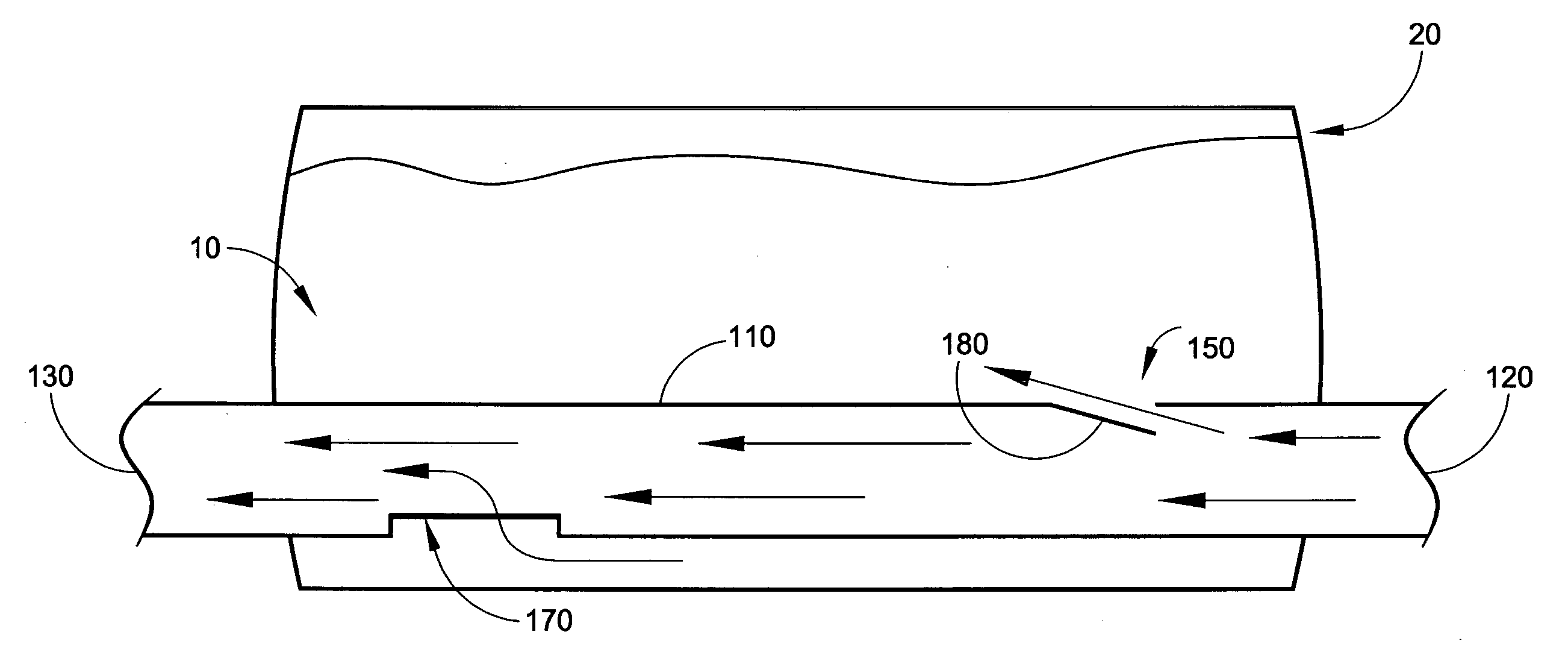
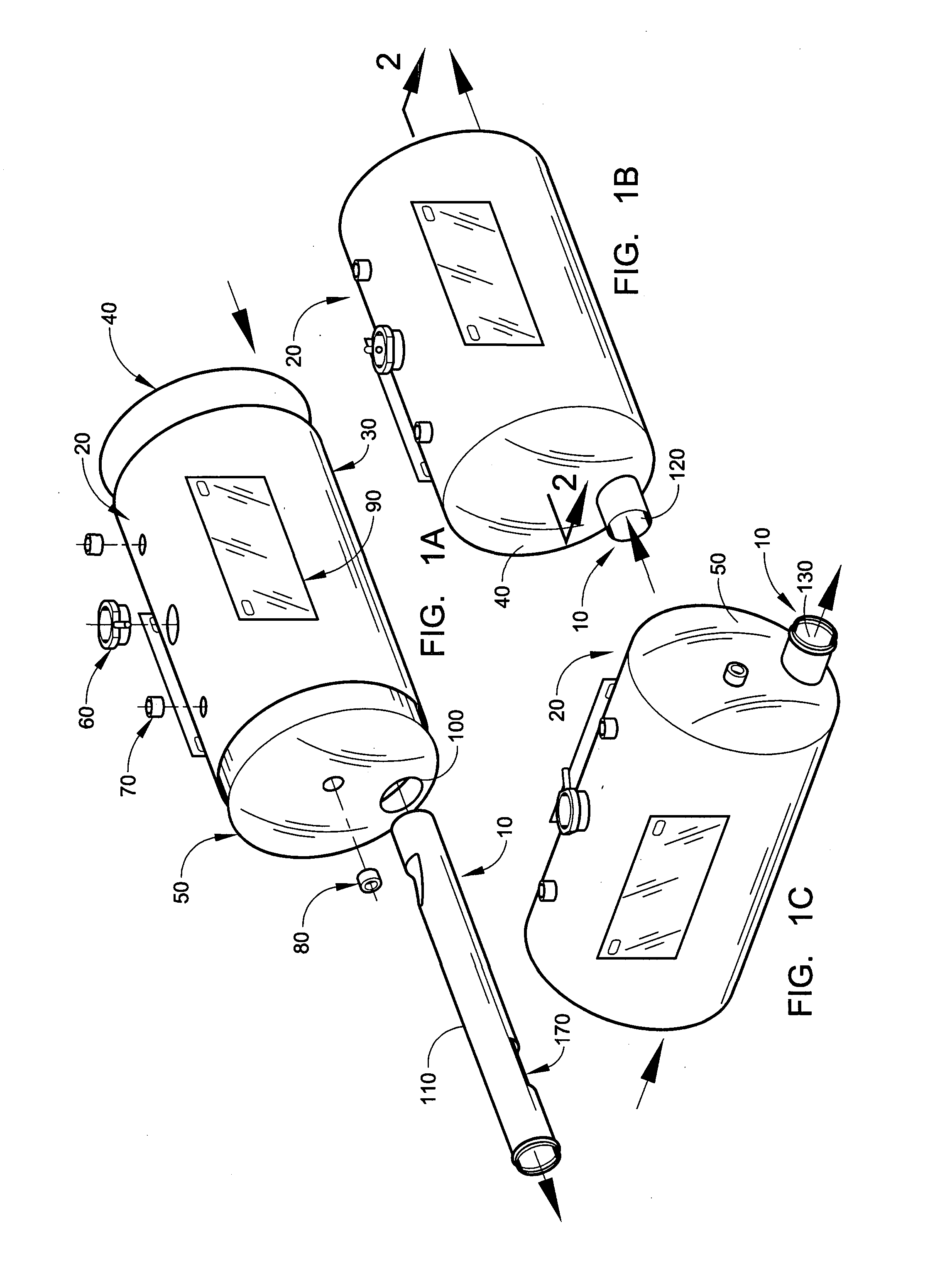
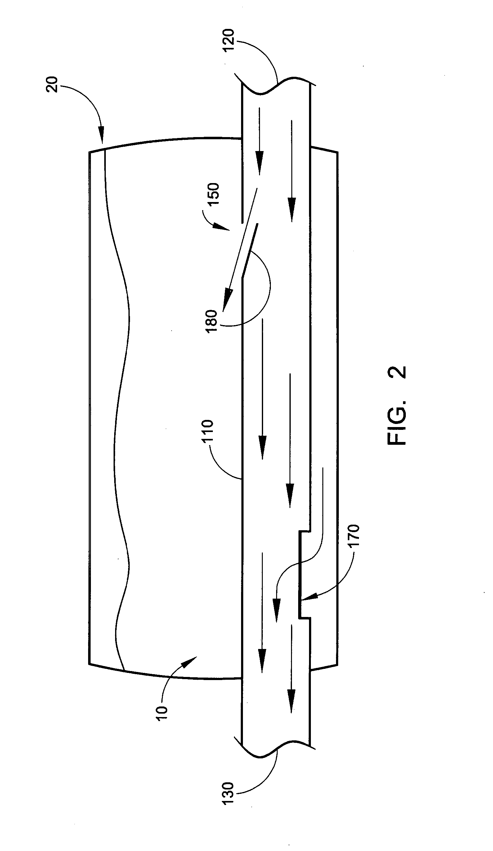
[0018]With reference to FIGS. 1-3, an embodiment of a deaeration device 10 for a coolant reservoir 20 of a hybrid transit bus cooling package for both engine and electronics cooling loops will be described. More particularly, the deaeration device has continuous deaerating capabilities and is part of a complete rooftop cooling package for a hybrid transit bus. Although the deaeration device 10 is described in conjunction with deaerating a cooling fluid, the deaeration device 10 may be used in other applications other than deaerating a cooling fluid, for example, but not by way of limitation, in an alternative embodiment, the deaeration device 10 is used for deaerating liquid fuel in a fuel line / system. Still further, the deaeration device 10 may be used in coolant reservoirs other than those of a hybrid transit bus cooling package and / or in cooling loops in addition to or other than engine and electronics cooling loops.

[0019]In the embodiment of the deaeration device 10 and the rese...


PUM


Abstract

A deaeration device for deaerating coolant fluid flow in a recirculation cooling system, where the recirculation cooling system includes a cooling fluid reservoir adapted to receive the deaeration device submerged within cooling fluid therein, includes an elongated deaeration tube including a fluid outlet and a deaerating skimming shaped slot for skimming air bubbles and cooling fluid from cooling fluid flow flowing through the deaeration tube, and including a fluid inlet for allowing the same amount of fluid that is skimmed off and removed through the top fluid outlet to re-enter the deaeration tube to maintain mass balance in the cooling fluid flow.

Description

FIELD OF THE INVENTION[0001]The field of the invention relates to deaeration devices for removing air bubbles from liquid flow that has air bubbles in the fluid flow.BACKGROUND OF THE INVENTION[0002]When air bubbles exist in the fluid medium for any kind of heat transfer application, they can potentially attach themselves to any surface and act as an insulator, preventing heat transfer between the fluid medium and the heated and cooled surfaces. In a transportation application, this exists in the radiators cores and other components in the cooling loop. By way of example but not limitation, in a hybrid-electric drive system this includes engine radiators, engine, heater core, electric motors, generators, braking resistors, and inverters. Any surface that transfers heat into or out from the cooling fluid will suffer a performance reduction if air bubbles are present in the fluid.SUMMARY OF THE INVENTION[0003]An aspect of the present invention involves a deaeration device that utilize...

Claims


Application Information

Patent Timeline
IPC IPC(8): B01D19/00
CPCB01D19/0063B01D19/0042
Inventor FOLLETTE, DAVID J.STONE, KEVIN T.
Owner SHEPPARD MULLIN RICHTER & HAMPTON
Why Eureka
Try Eureka