Method for Connecting Printed Circuit Board

a technology of printed circuit board and connection plate, which is applied in the direction of printed circuit aspects, non-metallic protective coating applications, adhesive types, etc., can solve the problems of less physical strength of solder connection portions of fine pitches, less connection stability, and increased likelihood of short-circuit with adjacent connection portions, so as to improve the high temperature characteristics of thermosetting adhesive composition, improve the effect of chemical resistance and relatively mild setting process

Inactive Publication Date: 2008-05-15
3M INNOVATIVE PROPERTIES CO
View PDF3 Cites 10 Cited by
  • Summary
  • Abstract
  • Description
  • Claims
  • Application Information

AI Technical Summary

Benefits of technology

[0048]In an embodiment of the invention, a bis-phenol A diglycidyl ether type epoxy resin (hereinafter called “diglycidyl ether type epoxy resin”) can be used as the preferred epoxy resin. This diglycidyl ether type epoxy resin is liquid and can improve high temperature characteristics of the thermosetting adhesive composition, for example. When this diglycidyl ether type epoxy resin is used, chemical resistance due to setting at a high temperature and a glass transition temperature, for example, can be improved. It will make it possible to use a various curing agents and setting process will be relatively mild. Such a diglycidyl ether type epoxy resin is commercially available from Dow Chemical (Japan) Co. under the trade name D.E.R. 332.

Problems solved by technology

However, pitches between the connection portions on the FPC become miniaturized, and as the pitches become smaller, a problem of short-circuit with the adjacent connection portions becomes more likely to occur.
In addition, another problem exists in that physical strength of the solder connection portions of the fine pitches is low and connection stability is inferior.

Method used


Image

  • Method for Connecting Printed Circuit Board
  • Method for Connecting Printed Circuit Board
  • Method for Connecting Printed Circuit Board

Examples


example 1

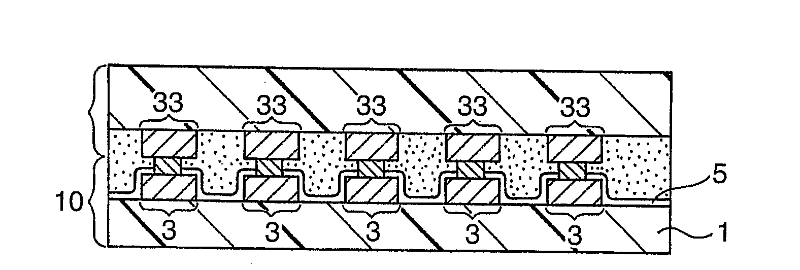
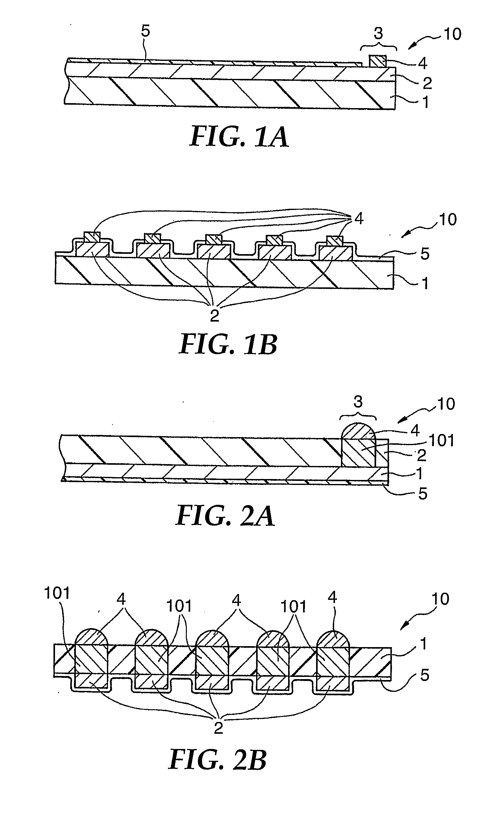
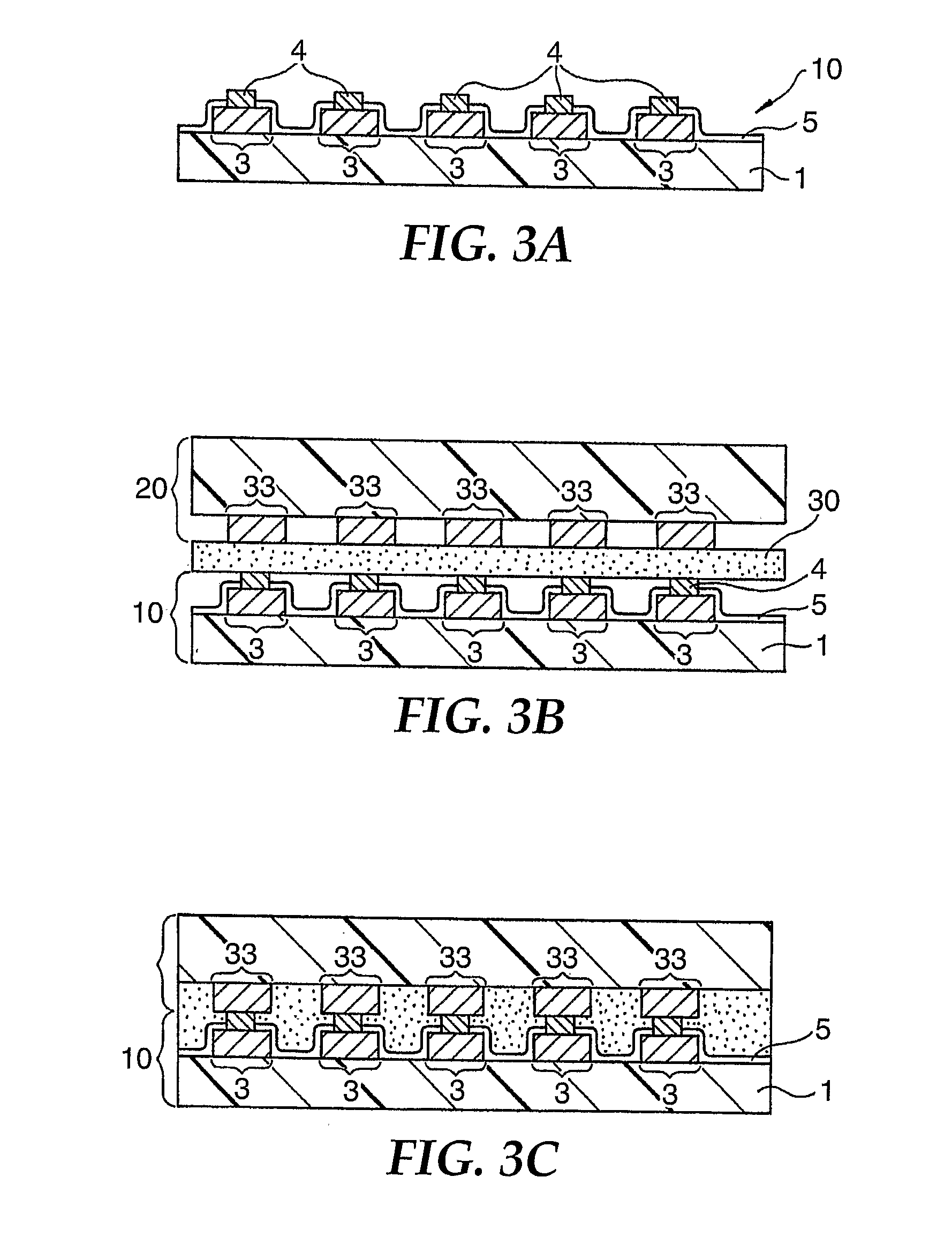
[0052]An FPC equipped with a bump structure that has a construction shown in FIG. 1 is prepared. More concretely, the FPC has a construction in which each copper bump 4 is formed by plating on a connection portion 3 (land) at the distal end of a wire 2 (thickness: 15 μm, width 36 μm) formed of a copper lead on a resin film 1 (25 μm thick) formed of polyimide, and the surface of the bump is plated with gold (Au). The bump 4 has a width of 36 μm, a length of 60 μm, and a height of 15 μm.

[0053]The same FPC as described above with the exception that the bump is not formed is used as the second wiring board to which the FPC is to be connected.

[0054]The adhesive film is obtained by forming a liquid composition tabulated in Table 2, coating the liquid composition on a polyethylene terephthalate (PET) film the PET film having been release treated with silicone and drying the film at 100° C. for 30 minutes to a thickness of 25 μm.

[0055]The adhesive film is put on the FPC equipped with the bu...


PUM

PropertyMeasurementUnit
heightaaaaaaaaaa
lengthaaaaaaaaaa
lengthaaaaaaaaaa

Abstract

To provide a PCB that does not generate a short-circuit problem even at a very small pitch and has high connection reliability a method is provided for connecting a printed circuit board (PCB) to a second circuit board comprising: providing a printed circuit board (PCB) having a connection portion; providing a second circuit board having a connection portion, the second circuit board to be connected to the PCB, wherein the connection portion of one or both of the PCB and second circuit board has at least one conductive bump, positioning the connection portion of the PCB opposite the connection portion of the second circuit board with a thermosetting adhesive film between the connection portions of the PCB and second circuit board, and applying heat and pressure to the connection portions and the thermosetting adhesive film such that the adhesive film is displaced sufficiently to allow electrical contact between the at least one bump and the connection portion of the opposing circuit board and such that the heat is sufficient to cause the adhesive to set. Also provided is an article comprising a PCB having a connection portion with at least one conductive bump, and a thermosetting adhesive film on the surface of the connection portion.

Description

TECHNICAL FIELD[0001]This invention relates to a method for connecting a printed circuit board (PCB) to another circuit board (wiring board) or to an article that is used for the above method.BACKGROUND ART[0002]Electronic appliances such as digital cameras, cellular telephones, printers, and so forth, use in many cases a printed circuit board including a flexible printed circuit board (FPC; hereinafter merely called “FPC”) bonded to other wiring board. These electronic appliances are rendered small in size, and connection of the FPC having wires of fine pitches to other wiring board has been more and more required.[0003]When the FPC is connected to other wiring board, it has been customary in the past to employ a method that forms bumps on connection portions of the FPC, brings the bumps into contact with electrodes provided to other wiring board and solders them together to establish connection. However, pitches between the connection portions on the FPC become miniaturized, and a...

Claims


Application Information

Patent Timeline
Patent Type & Authority Applications(United States)
IPC IPC(8): H01R12/04C09J163/00H05K1/09H05K1/02
CPCH05K3/28H05K3/305H05K3/361H05K3/4007H05K2203/1189H05K2201/09481H05K2201/10977H05K2203/0733H05K2201/0367H05K3/36H05K1/14C09J5/06
Inventor SATOH, KAZUOYAMAZAKI, HIDEO
Owner 3M INNOVATIVE PROPERTIES CO
Why Eureka
Try Eureka