

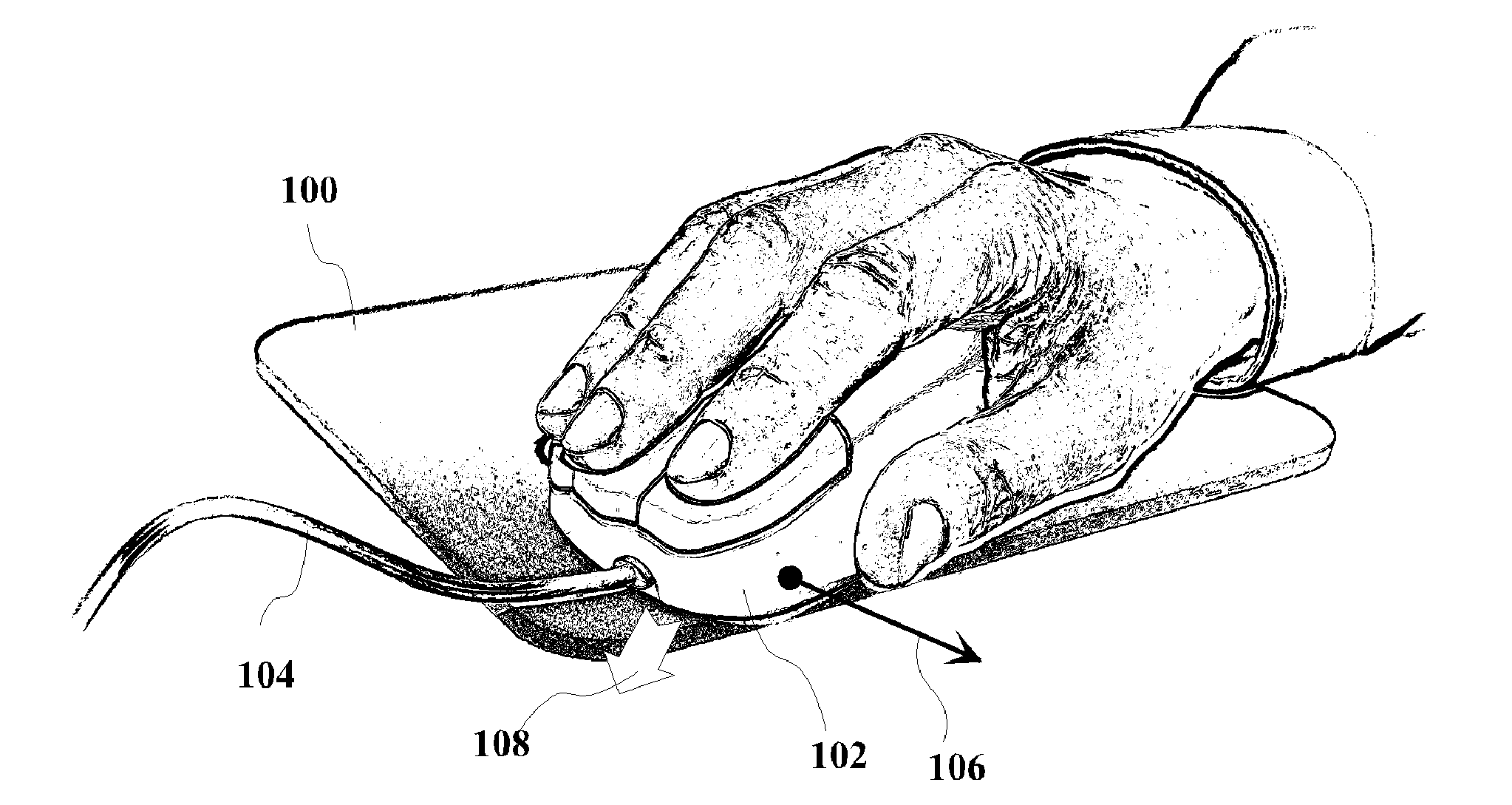
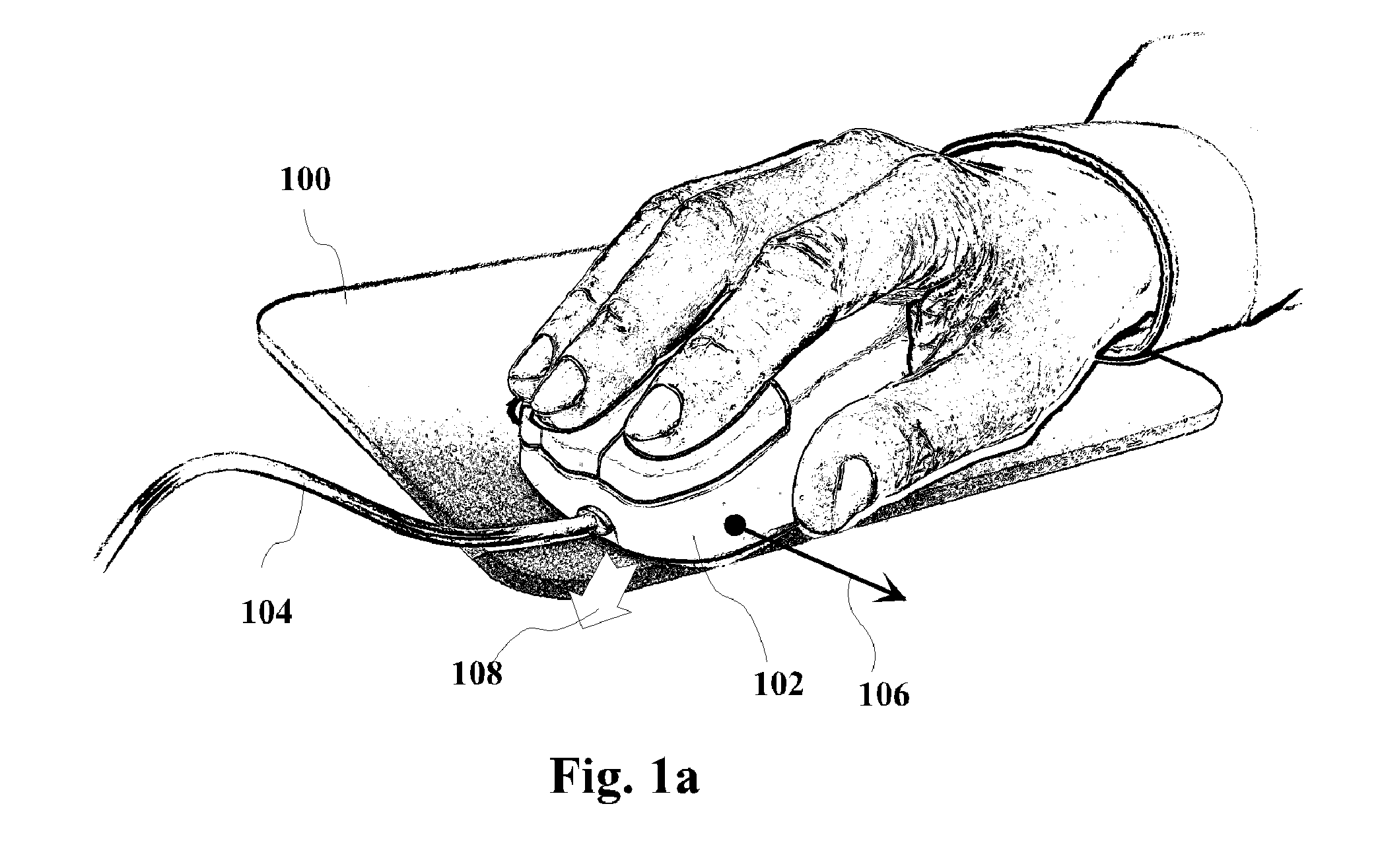
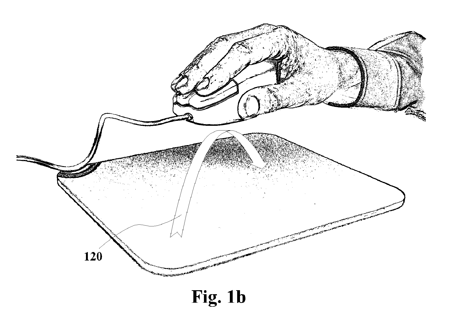
Self-propelled haptic mouse system
a mouse system and self-propelled technology, applied in the field of haptic mouse pointing devices, can solve the problems of mechanical slack that requires more acceleration to overcome, the development of a viable haptic mouse system producing directional force feedback, and the difficulty of reducing the reaction time of the mechanism
- Summary
- Abstract
- Description
- Claims
- Application Information
AI Technical Summary
Benefits of technology
Problems solved by technology
Method used
Image

Examples
first embodiment
[0049]In the first embodiment, shown in FIG. 3, an asynchronous dynamoelectric planar motor is employed to produce the propelling force. A stator part of the motor and a control circuit 312 are assembled in a bottom shell 302 of the mouse body. The stator part comprises a ferromagnetic core 306 that has multiple poles 308 extending through openings 304 flush with a bottom plane of shell 302. The stator also has multiple coils 310 that are connected to control circuit 312 and encompass different groups of stator poles 308 distributed in two dimensions along the bottom plane of shell 302. In this embodiment, mouse pad 100 has a built-in reaction plate, comprising a ferromagnetic layer 314 overcoated with an electrically conductive layer 318. To improve performance, ferromagnetic layer 314 can have multiple reaction poles 316 protruding through openings in conductive layer 318. The whole structure is laminated with a top layer 320, made of textile or plastic, that serves to ensure smoo...
second embodiment
[0053]In the second embodiment, exemplified in FIG. 5, the planar motor drive employs friction of rotating wheels against mouse pad 100 to produce the desired propelling force. In this particular design example, friction wheels 508 are made as single pieces with their shafts and are mounted between bearings 514 on a circular frame 510. The shafts of the adjacent wheels 508 end with bevel gear teeth and rotationally couple together inside bearings 514. Frame 510 is suspended on three brackets 512, flexibly attached to electromagnetic actuators 516 which are secured to the bottom shell 302 that, in turn, has slots 502 matching position of wheels 508. One of wheels 508 is coupled with a rubber band and pulley gear 520 to a rotary motor 518 that is also secured in shell 302. This design can conveniently accommodate a rolling ball 506 that can pass unobstructed through the whole assembly and extend through an aperture 504. In this embodiment, rolling ball 506 can be used to drive X-Y pos...
third embodiment
[0056]FIGS. 6 and 7 illustrate the present invention, where the motor drive includes a vibrating brush. The brush has a circular frame 602 and multiple bristles 604 that are radially slanted. The brush is mounted with flexible joints on three electromagnetic actuators 606 which are secured in a top shell 608 of the mouse body. The height of the assembly is adjusted such as bristles 604 of the brush are exposed through an aperture 610 in bottom shell 302 short of touching the underlying surface of mouse pad 100 which is textured to impede horizontal slippage of bristles 604. The control circuit applies power to actuators 606 in a form of repetitive electric pulses of variable amplitude, causing the brush to vibrate. In response to the received command, the control circuit changes power balance between actuators 606 such as to cause most intensive vibration on the brush side where bristles 604 are slanted in the desired direction. The vibrating bristles repetitively strike the surface...
PUM
 Abstract
Description
Claims
Application Information