Optical lens and method of manufacturing the same

a technology of optical lenses and liquid lenses, applied in the field of optical lenses, can solve the problems of increasing the the whole size of the camera module, and the problem of liquid lens related problems, so as to improve the efficiency of the actuator

Inactive Publication Date: 2008-05-15
SAMSUNG ELECTRONICS CO LTD
View PDF2 Cites 167 Cited by
  • Summary
  • Abstract
  • Description
  • Claims
  • Application Information

AI Technical Summary

Benefits of technology

[0029]A buffer elastic film may be provided on a bottom of the light-transmitting substrate, and the actuator may be provided on the buffer elastic film. The buffer elastic film may be formed of the same or a different material from the light-transmitting elastic film. Since the buffer elastic film is not a portion through which light is directly transmitted, unlike the light-transmitting elastic film, the buffer elastic film may be formed of a material having poor light-transmitting performance. Preferably, the buffer elastic film may be formed of a material having an elastic modulus equivalent to that of the light-transmitting elastic film to improve the efficiency of the actuator.

Problems solved by technology

However, when a camera module for a personal mobile terminal is manufactured to have these various advanced functions, the camera module is limited in its size, due to the size of a lens and a mechanical lens driving gear.
Since a separate motor or driver is required to control such variations, a problem occurs in that the whole size of the camera module increases.
However, the related art liquid lens has several problems.
Also, a problem occurs in that a high driving voltage is required to create the flow of fluid and to apply a hydraulic pressure to the fluid.
Furthermore, a problem occurs in that the response time required for focusing increases.
Moreover, when the hydraulic pressure (or flow) is applied to the fluid, a problem occurs in that it is difficult to dispense the exact amount of the fluid.
In particular, local strain unstably occurs in a boundary portion between a lens portion and a channel and thus the exact amount of the fluid is not dispensed.
This deteriorates reliability and stability.

Method used


Image

  • Optical lens and method of manufacturing the same
  • Optical lens and method of manufacturing the same
  • Optical lens and method of manufacturing the same

Examples


Embodiment Construction

[0043]Reference will now be made in detail to the exemplary embodiments of the present invention, examples of which are illustrated in the accompanying drawings, wherein reference numerals of elements are used consistently throughout this specification. The exemplary embodiments are described below to explain the present invention by referring to the figures. The detailed description of the known function or constitution may be omitted to clarify the subject matter of the present invention.

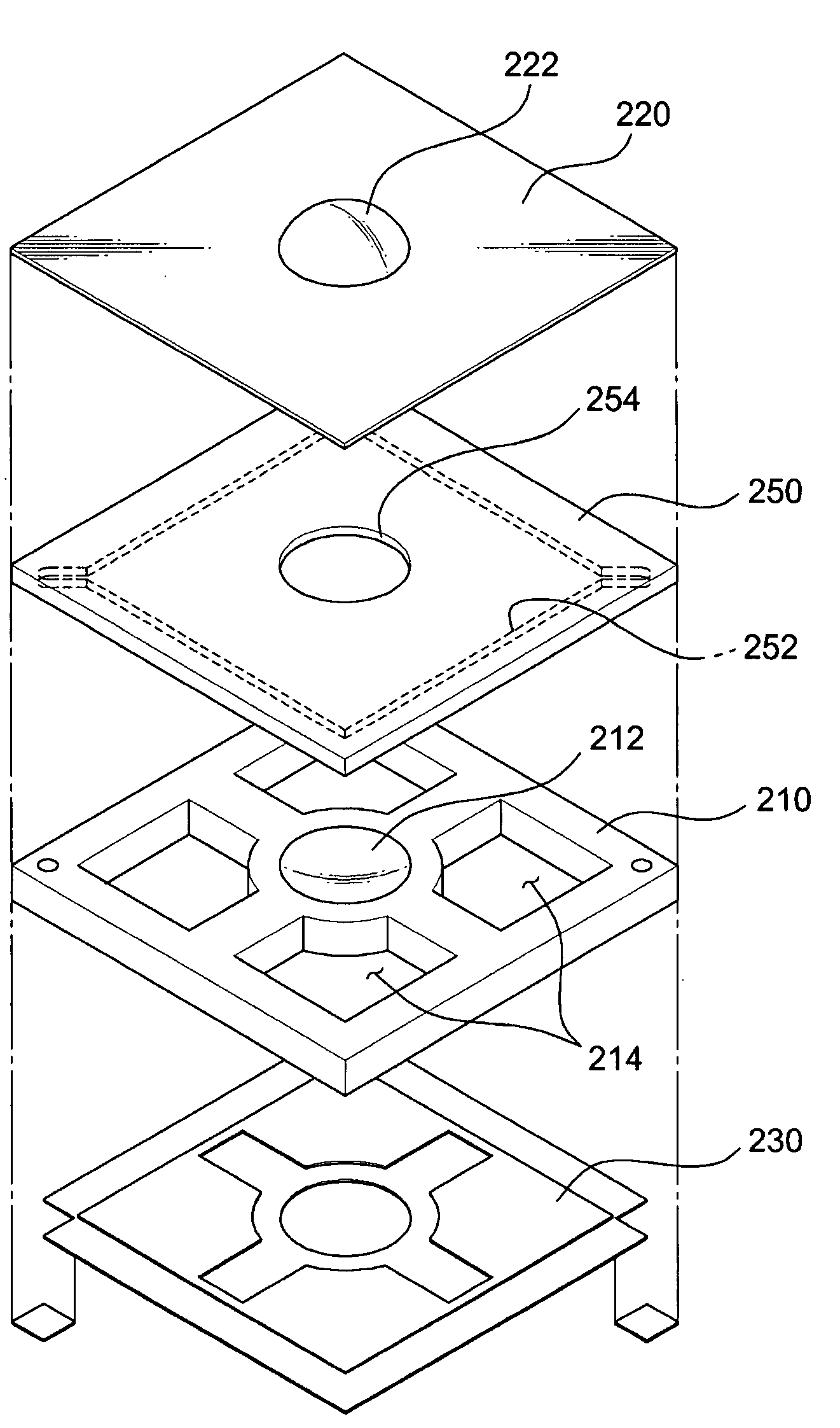
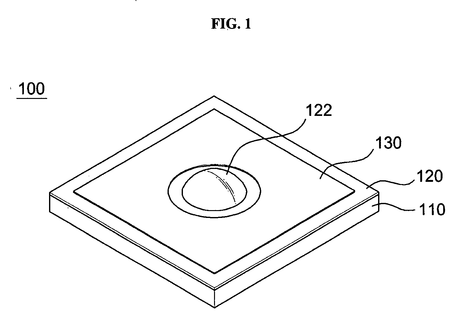
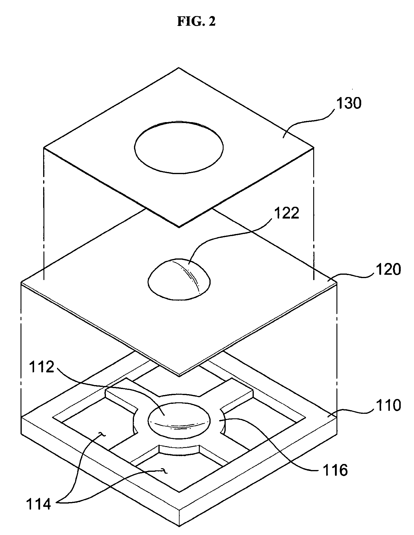
[0044]FIG. 1 is a perspective view illustrating a structure of an optical lens according to an exemplary embodiment of the present invention. FIGS. 2 and 3 are an exploded perspective view and a partially cut perspective view, respectively, illustrating a structure of an optical lens according to an exemplary embodiment of the present invention. FIG. 4 is a sectional view illustrating a structure of an optical lens according to an exemplary embodiment of the present invention.

[0045]An optical lens...


PUM


Abstract

An optical lens is provided. The optical lens provides miniaturization and thin size, and reduces the cost and improves productivity by simplifying the structure and manufacturing process. The optical lens includes a light-transmitting substrate with a lens chamber and a fluidic chamber that are connected with each other. The optical lens also includes a light-transmitting elastic film which seals the lens chamber, a buffer elastic film which seals the fluidic chamber, and an actuator on the buffer elastic film which corresponds to the fluidic chamber, and varies the volume of the fluidic chamber to vary a pressure acting on the light-transmitting elastic film.

Description

CROSS-REFERENCE TO RELATED APPLICATIONS[0001]This application claims priority from Korean Patent Application No. 10-2006-0111723, filed on Nov. 13, 2006 in the Korean Intellectual Property Office, the disclosure of which is incorporated herein by reference.BACKGROUND OF THE INVENTION[0002]1. Field of the Invention[0003]Apparatuses and manufacturing methods consistent with the present invention relate to an optical lens, and more particularly, to a variable focus optical lens that provides miniaturization and thin size, and reduces the cost and improves productivity by simplifying the structure and manufacturing process.[0004]2. Description of the Related Art[0005]In general, an optical lens is a transparent body or lens having at least two refractive curves. The optical lens is widely used in various applications, such as cameras, telescopes, and microscopes.[0006]For example, a camera module using an optical lens is used for a personal mobile terminal, such as a cellular phone or a...

Claims


Application Information

Patent Timeline
Patent Type & Authority Applications(United States)
IPC IPC(8): G02B3/14
CPCG02B7/026G02B3/14G02B3/005G02B7/021G02B1/06
Inventor CHOI, SEUNG TAELEE, SEUNG WANKIM, WOON BAECHOI, MIN SEOGLEE, EUN SUNGJUNG, KYU DONG
Owner SAMSUNG ELECTRONICS CO LTD
Why Eureka
Try Eureka