Fuel Cell System

a fuel cell and system technology, applied in the field of fuel cell systems, can solve the problems of overcharging a secondary battery, affecting the efficiency of the secondary battery, and releasing hydrogen gas to the outside, and achieve the effect of reducing the amount of fuel gas consumption and simple configuration

Inactive Publication Date: 2008-05-15
TOYOTA JIDOSHA KK
View PDF14 Cites 2 Cited by
  • Summary
  • Abstract
  • Description
  • Claims
  • Application Information

AI Technical Summary

Benefits of technology

[0038]According to the fuel cell system of the present invention as described above, it is possible to achieve a simple configuration and to appropriately reduce the amount of consumption of fuel gas while suitably circulating the fuel gas at the end of the operation or the like.

Problems solved by technology

If the pressure difference (differential pressure between electrodes) is large, however, it may induce the release of hydrogen gas to the outside due to deterioration of a fuel cell or a cross leakage therein.
Consequently, it could lead to an increase in wasteful consumption of hydrogen gas, to overcharge of a secondary battery, or to a need for a long time before completion of the operation.
In addition, the check valve (switch device) is disposed in the gas circulation system, which correspondingly results in hindering an efficient circulation of hydrogen gas when driving the pump at the end of the operation.
Also in the configuration disclosed in patent document 2, the same problem as the above may occur when it is attempted to reduce the hydrogen gas pressure at the end of the operation.
In addition, a plurality of shut-off valves and check valves are disposed in the gas circulation system, which correspondingly results in further hindering the circulation of the hydrogen gas.
The pump, however, cannot be driven and therefore it is difficult to generate power of the fuel cell at the rated operation pressure or lower.
Furthermore, a pressure loss of the hydrogen gas occurs at the shut-off valves or check valves in the gas circulation system when operating the fuel cell system in both patent documents.

Method used


Image

  • Fuel Cell System
  • Fuel Cell System
  • Fuel Cell System

Examples


Embodiment Construction

[0042]A fuel cell system according to a preferred embodiment of the present invention will be described below with reference to accompanying drawings.

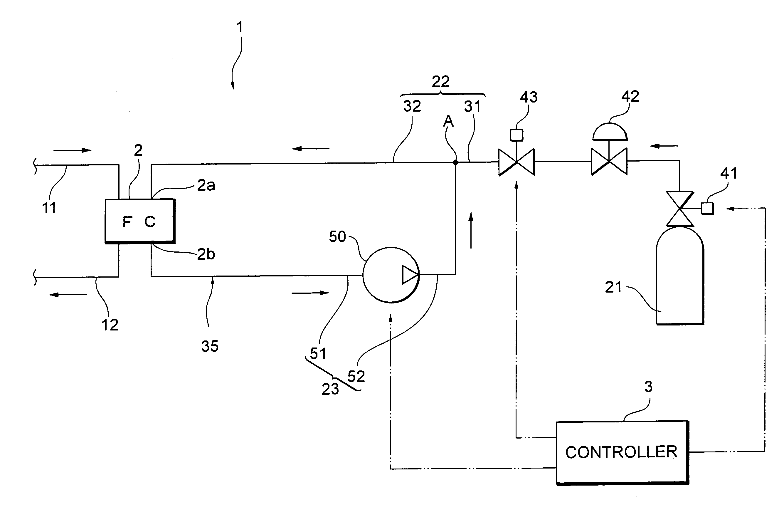
[0043]The fuel cell system is simplified in system configuration by improving the arrangement of the switch devices such as valves disposed in a piping line for hydrogen gas as fuel gas. Furthermore, the fuel cell system is designed to reduce the amount of consumption of the hydrogen gas at the end of the system operation.

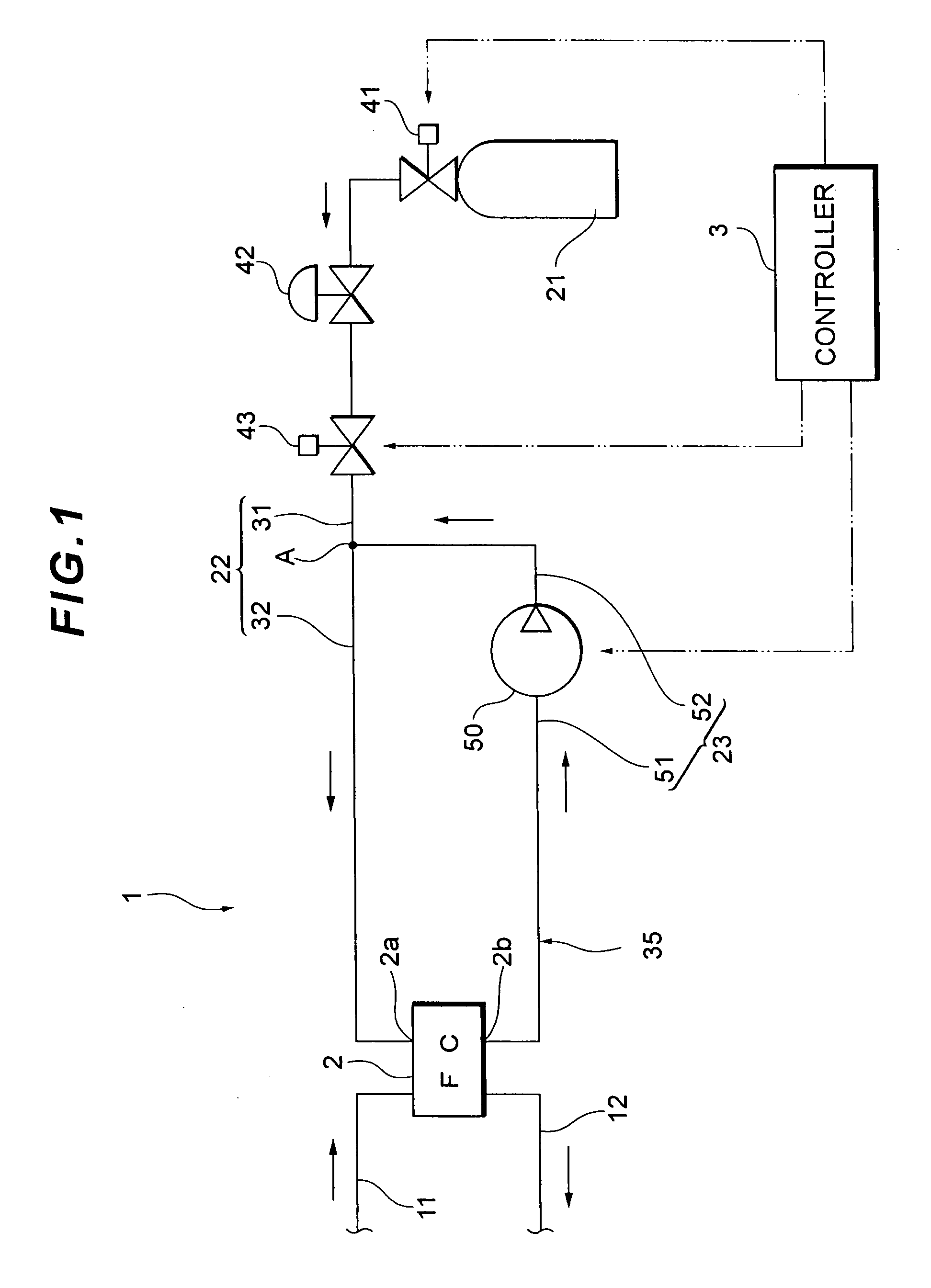
[0044]As shown in FIG. 1, the fuel cell system 1, which is mounted on, for example a fuel cell vehicle, includes a fuel cell 2 having a stack structure in which a lot of single cells are stacked and a controller 3 for overall controlling the entire system. As for the fuel cell 2, there are several types of fuel cells including a phosphoric-acid type. The fuel cell 2, however, is of solid polymer electrolyte type, which is suitable for in-vehicle and stationary applications here.

[0045]The single cell in the fuel cell 2...


PUM

PropertyMeasurementUnit
pressureaaaaaaaaaa
pressureaaaaaaaaaa
pressureaaaaaaaaaa

Abstract

It is an object to provide a simple fuel cell system and to provide a fuel cell system capable of reducing the amount of consumption of fuel gas at the time of completion of operation. A fuel cell system includes a supply piping from a fuel gas supply source storing fuel gas to a gas inlet of a fuel cell and a circulation piping from a gas outlet of the fuel cell to a junction at which the circulation piping joins the supply piping. A regulating valve and a shut-off valve are disposed on the upstream side of the junction in the supply piping. A portion on the downstream side of the junction in the supply piping and the circulation piping are in constant communicated.

Description

TECHNICAL FIELD[0001]The present invention relates to a fuel cell system for circulating fuel gas discharged from a fuel cell back to the fuel cell.BACKGROUND ART[0002]A fuel cell system, which circulating hydrogen gas (surplus hydrogen) as fuel gas from a fuel cell to the fuel cell, is widely known (for example, refer to patent documents 1 and 2). A fuel gas piping line for this type of fuel cell system includes a supply piping from a fuel gas supply source such as a high pressure tank to a gas inlet of the fuel cell and a circulation piping from a gas outlet of the fuel cell to a junction at which the circulation piping joins the supply piping. In other words, the gas circulation system for circulating hydrogen gas to the fuel cell includes the circulation piping and a portion on the downstream side of the junction in the supply piping.[0003]For example, in patent document 1, a shut-off valve and a regulating valve are disposed in order from the fuel gas supply source side on the ...

Claims


Application Information

Patent Timeline
Patent Type & Authority Applications(United States)
IPC IPC(8): H01M8/02H01M8/04
CPCH01M8/04097H01M8/04223H01M8/0432H01M8/0438Y02E60/50H01M8/04761H01M8/0625H01M8/0662H01M2008/1095H01M8/04753H01M8/04228
Inventor YAMAMOTO, KATSUHIKOYUMITA, OSAMUKANIE, NAOKIYOSHIDA, NAOHIRO
Owner TOYOTA JIDOSHA KK
Why Eureka
Try Eureka