
Traffic Information Interpolation System

a traffic information and interpolation system technology, applied in the field of interpolation of traffic information, can solve the problems of inability to properly perform information display or route search in the car navigation system, and inability to collect floating car data spatial and temporal deficiency, etc., to achieve high precision, stable and highly precise spatial interpolation results

Active Publication Date: 2008-05-15
HITACHI LTD
View PDF1 Cites 33 Cited by
  • Summary
  • Abstract
  • Description
  • Claims
  • Application Information

AI Technical Summary

Benefits of technology

[0011]This invention can be applied to provide traffic interpolation data for traffic information services which use FCD. This invention can provide high precision traffic interpolation data on the basis of the spatial correlation on road-links, especially in case where the FCD missing rate is very high.
[0012]By dynamically selecting bases depending on road-links on which real-time FCD were collected, stable and highly precise spatial interpolation results can be obtained even when the number of real-time FCD components is very small.

Problems solved by technology

However, the random routes and data collecting timings of floating cars lead to a spatial and temporal deficiency in the collected floating car data (hereafter referred to as FCD for brevity).
Information display or route search in a car navigation system cannot be properly performed if there are such deficiencies in the collected traffic information.
However, these conventional Interpolation techniques have the following problems.
Accordingly, even if the interpolation of the road-links having missing traffic information by using the traffic information of neighboring links is attempted, such an attempt will fail because situations occur frequently where the traffic information of the neighboring links are all missing as well.
If the interpolation of the road-links having missing traffic information is performed by using the traffic information on remote road-links, the precision in interpolation is very poor in an area where the connections among the road-links are complicated so that the traffic information obtained through interpolation becomes far different from the actual real-time traffic information.
On the other hand, if the process of statistically treating the past FCD is used, the interpolation of FCD with a high rate of link data missing is indeed possible, but the statistically processed traffic information will not exactly reflect the real-time traffic information.
However, if the spatial missing rate of road-link data is extremely high, the amount of the link data affecting the result of interpolation is insufficient and it may happen that the precision in the resulted interpolation is poor.
So, when the link data missing rate is extremely high, it is hardly possible that the link data on the neighboring links that affect the link data of the links subjected to interpolation were sufficiently collected.
If the spatial interpolation is performed with very scarce spatial samples, using the technique disclosed in JP-A-2005-004668, the resulted precision becomes poor.
Since, however, the road-links on which real-time FCD can be collected do not necessarily have strong correlation to the selected bases, the scarcity of samples may still lead to unstable outputs.

Method used


Image

  • Traffic Information Interpolation System
  • Traffic Information Interpolation System
  • Traffic Information Interpolation System

Examples


embodiment 1

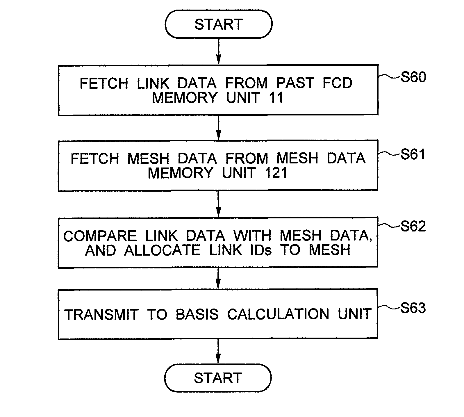
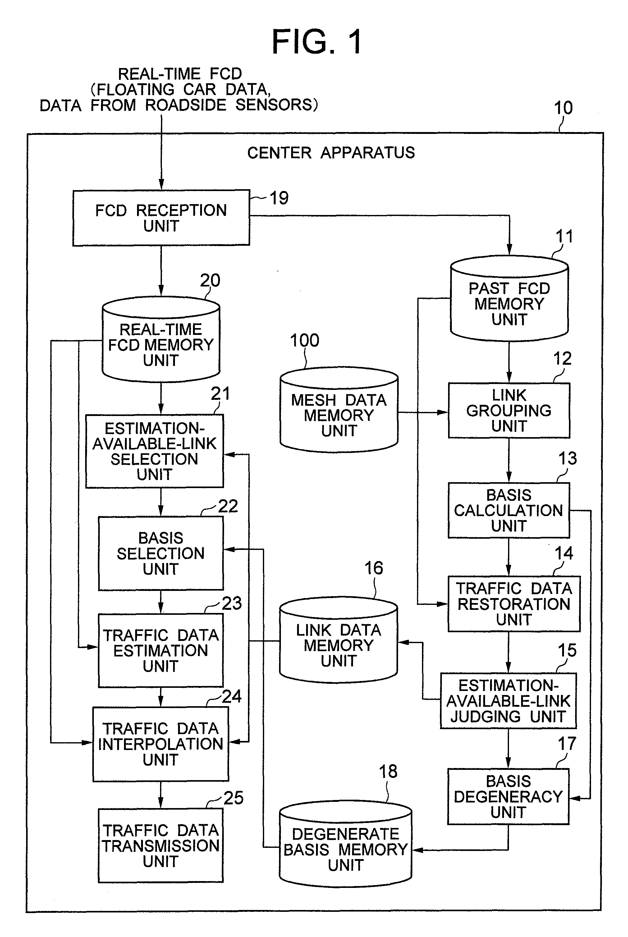
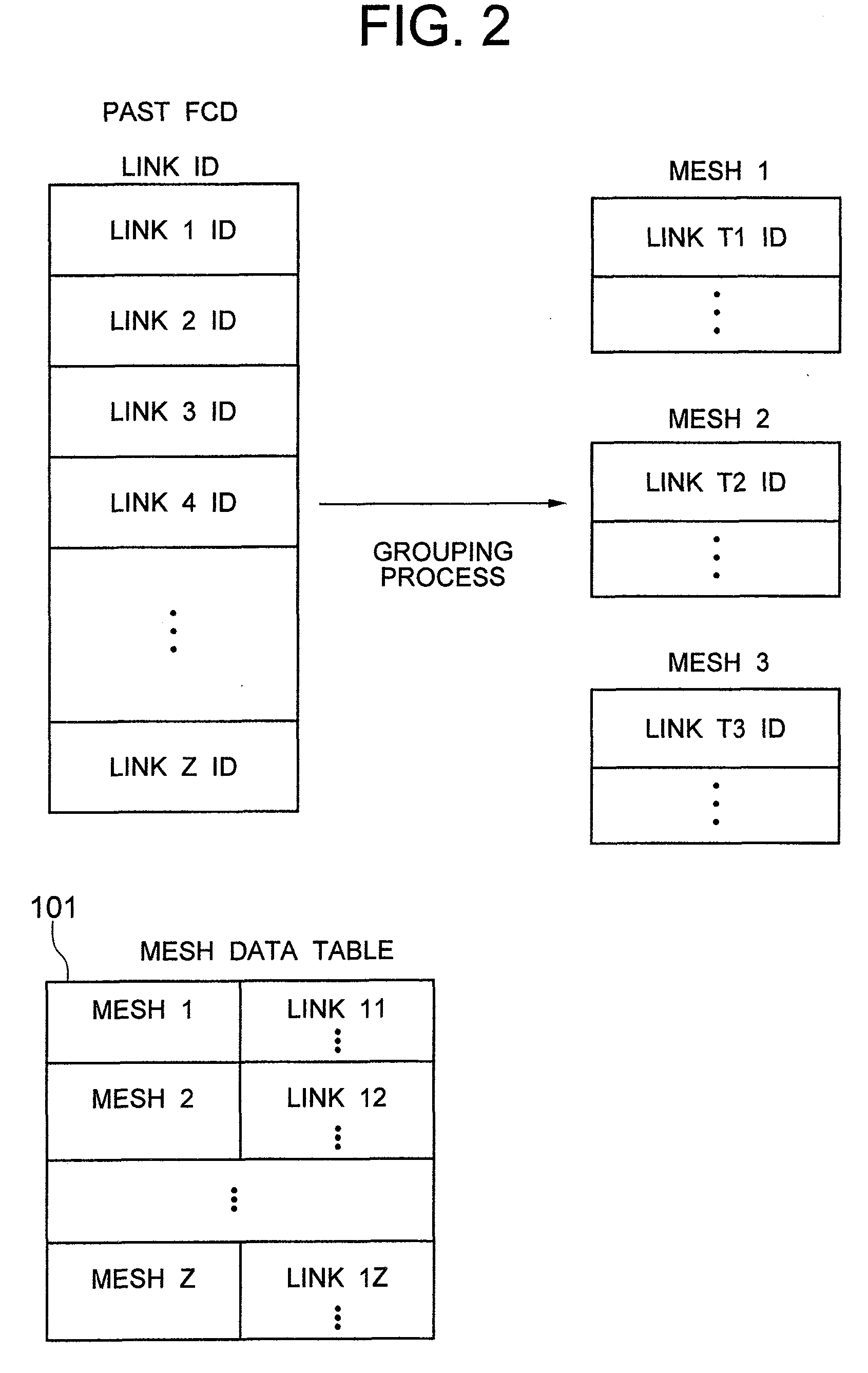
[0034]FIG. 1 is a functional block diagram for a traffic data collection / distribution system as an embodiment of this invention. As Shown in FIG. 1, the traffic data collection / distribution system consists mainly of a center apparatus 10. The center apparatus 10 comprises a past FCD memory unit 11; a basis calculation unit 13; a link grouping unit 12; a traffic data restoration unit 14; an estimation-available-link judging unit 15; a link data memory unit 16; a basis degeneracy unit 17; a degenerate basis memory unit 18; an FCD reception unit 19; a real-time FCD memory unit 20; an estimation-available-link selection unit 21; a basis selection unit 22; a traffic data estimation unit 23; a traffic data interpolation unit 24; a traffic data transmission unit 25; and a mesh data memory unit 100.

[0035]In the center apparatus 10, the past FCD memory unit 11 stores the FCD received by the FCD reception unit 19 in the past. The stored, past FCD are administrated by the link IDs attached to ...

embodiment 2

[0086]FIG. 16 shows a variation of the traffic data system as the embodiment of this invention shown in FIG. 1. In this modified embodiment, the whole system is divided into three sections: traffic data transmission apparatus 30, vehicle-borne terminal apparatus 31 and traffic data center apparatus 200. Further, the degenerate basis generation function and the link data generation function are located in the traffic data center apparatus 200, and the traffic data interpolation function is situated in the vehicle-borne terminal apparatus 31. The traffic data transmission apparatus 30 and the vehicle-borne terminal apparatus 31 can communicate with each other through communication networks (not shown) such as portable telephone channels or the Internet. Or the data transmitted from the traffic data transmission apparatus 30 may be received by the vehicle-borne terminal apparatus 31 through broadcasting channels such as FM multiple broadcasting channels or terrestrial digital broadcast...


PUM


Abstract

In a traffic information system, the principal component analysis of the floating car data collected in the past is performed for each traffic area. From among the bases representing the traffic data collected on the road-links in the traffic area, the bases which have strong correlation to the road-links on which real-time traffic data were collected are selected. The weighting coefficients for the selected bases are calculated by projecting the real-time traffic data onto the selected bases. The traffic estimation data are calculated by linearly combining the selected bases with the obtained weighting coefficients as the coefficients of the respective bases. The calculated traffic estimation data are used for the interpolation of the road-links on which the real-time traffic data were not collected.

Description

BACKGROUND OF THE INVENTION[0001]This invention relates to the interpolation of traffic information.[0002]As compared with a traffic information system which collects traffic information from roadside sensors, a floating car system can collect traffic information over a broader area at a lower cost. However, the random routes and data collecting timings of floating cars lead to a spatial and temporal deficiency in the collected floating car data (hereafter referred to as FCD for brevity). Information display or route search in a car navigation system cannot be properly performed if there are such deficiencies in the collected traffic information. Therefore, it is necessary to interpolate the FCD if they are to be used for such applications.[0003]A technique for imputing the traffic information collected by roadside sensors is disclosed in, for example, JP-A-7-129893. According to the artifice disclosed there, deficiency in traffic information on a certain road-link is interpolated w...

Claims


Application Information

Patent Timeline
Patent Type & Authority Applications(United States)
IPC IPC(8): G06F17/18
CPCG08G1/0104
Inventor HIRUTA, TOMOAKIKUMAGAI, MASATOSHITANIKOSHI, KOICHIRO
Owner HITACHI LTD
Learn More