Wild frequency avionic refrigeration system and controller therefor

a refrigeration system and avionic technology, applied in refrigeration components, dc circuits to reduce harmonics/ripples, light and heating apparatus, etc., can solve the problems of electromechanical position sensors such as hall effect sensors that are prone to malfunction or failure, and the position sensor data that is communicated by wires is not well suited to avionic applications

Active Publication Date: 2008-05-22
BE AEROSPACE INCORPORATED
View PDF18 Cites 88 Cited by
  • Summary
  • Abstract
  • Description
  • Claims
  • Application Information

AI Technical Summary

Benefits of technology

[0004]In one aspect, an avionic refrigeration system is provided. The refrigeration system is powered by a wild frequency AC power supply, the frequency of which varies according to the speed (i.e., RPM) of the aircraft's engines, and the system includes: a refrigeration LRU configured to store food and beverages, the refrigeration LRU comprising a vapor cycle system including a brushless DC compressor motor, a brushless DC condenser motor, a brushless DC evaporator motor and a plurality of sensors configured to output operating parameter data relative to the vapor cycle system; a power module configured to convert a wild frequency AC input voltage to at least one DC output voltage; a motor control module in communication with the brushless DC compressor motor, the brushless DC condenser motor and the brushless DC evaporator motor; and a processing module in communication with the plurality of sensors and the motor control module, wherein the processing module, according to the operating parameter data, outputs control signals to the motor control module for independently driving the brushless DC compressor motor, the brushless DC condenser motor and the brushless DC evaporator motor. In some embodiments of the refrigeration system, a refrigeration unit controller includes the power module, the motor control module and the processing module.
[0005]In another aspect, a controller is provided for a refrigeration LRU configured to store food and beverages, wherein the refrigeration unit LRU includes a vapor cycle system having a brushless DC compressor motor, a brushless DC condenser motor, a brushless DC evaporator motor and a plurality of sensors configured to output operating parameter data relative to the vapor cycle system. The controller includes: a power module configured to convert a wild frequency AC input voltage to at least one DC output voltage; a motor control module in communication with the brushless DC compressor motor, the brushless DC condenser motor and the brushless DC evaporator motor; and a processing module in communication with the plurality of sensors and the motor control module, wherein the processing module, according to the operating parameter data, outputs control signals to the motor control module for independently driving the brushless DC compressor motor, the brushless DC condenser motor and the brushless DC evaporator motor.

Problems solved by technology

Such conventional avionic refrigeration systems have a number of drawbacks, largely stemming from the construction of the refrigeration LRU.
While AC induction motors are used for many applications due to their low cost and ruggedness, AC induction motors are not well suited to avionic applications due to their large size, weight and difficulty to accurately and variably control.
Disadvantageously, in an avionic environment, sensor wiring may be aggregated with other power, control and communication wiring in a wiring harness causing position sensor data that is communicated by the wires to be corrupted due to harness crosstalk, electromagnetic interference (EMI) or the like.
Furthermore, electromechanical position sensors such as Hall Effect sensors are prone to malfunction or failure over time due to wear and tear.
When such a sensor malfunctions or fails, the motor cannot be controlled and must be replaced or repaired.
Moreover, in the context of a refrigeration unit, it is difficult to reliably employ a Hall Effect sensor in a compressor due to the compressor being sealed and containing refrigerant and oil.

Method used


Image

  • Wild frequency avionic refrigeration system and controller therefor
  • Wild frequency avionic refrigeration system and controller therefor
  • Wild frequency avionic refrigeration system and controller therefor

Examples


Embodiment Construction

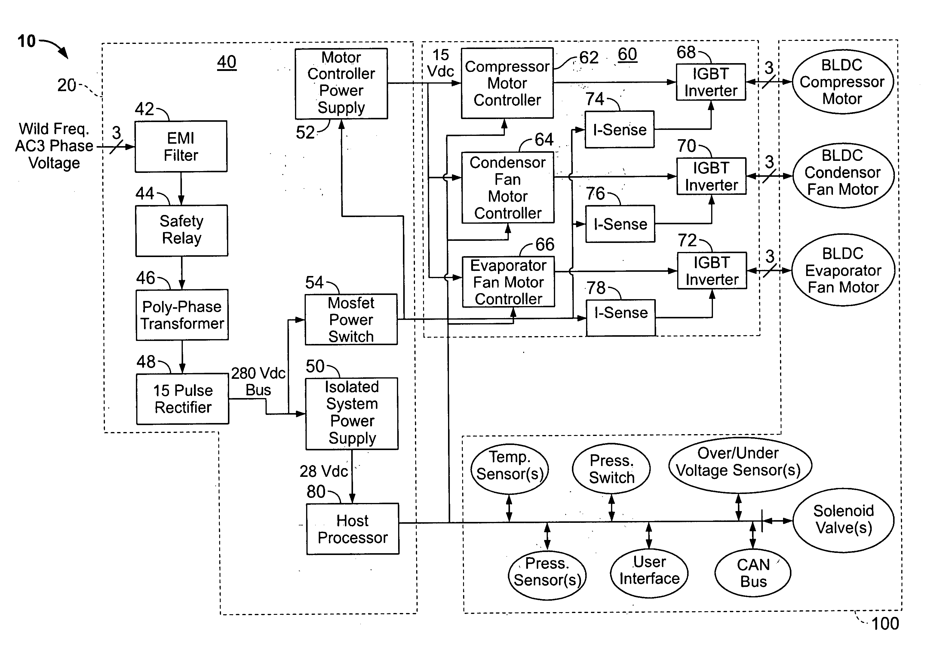
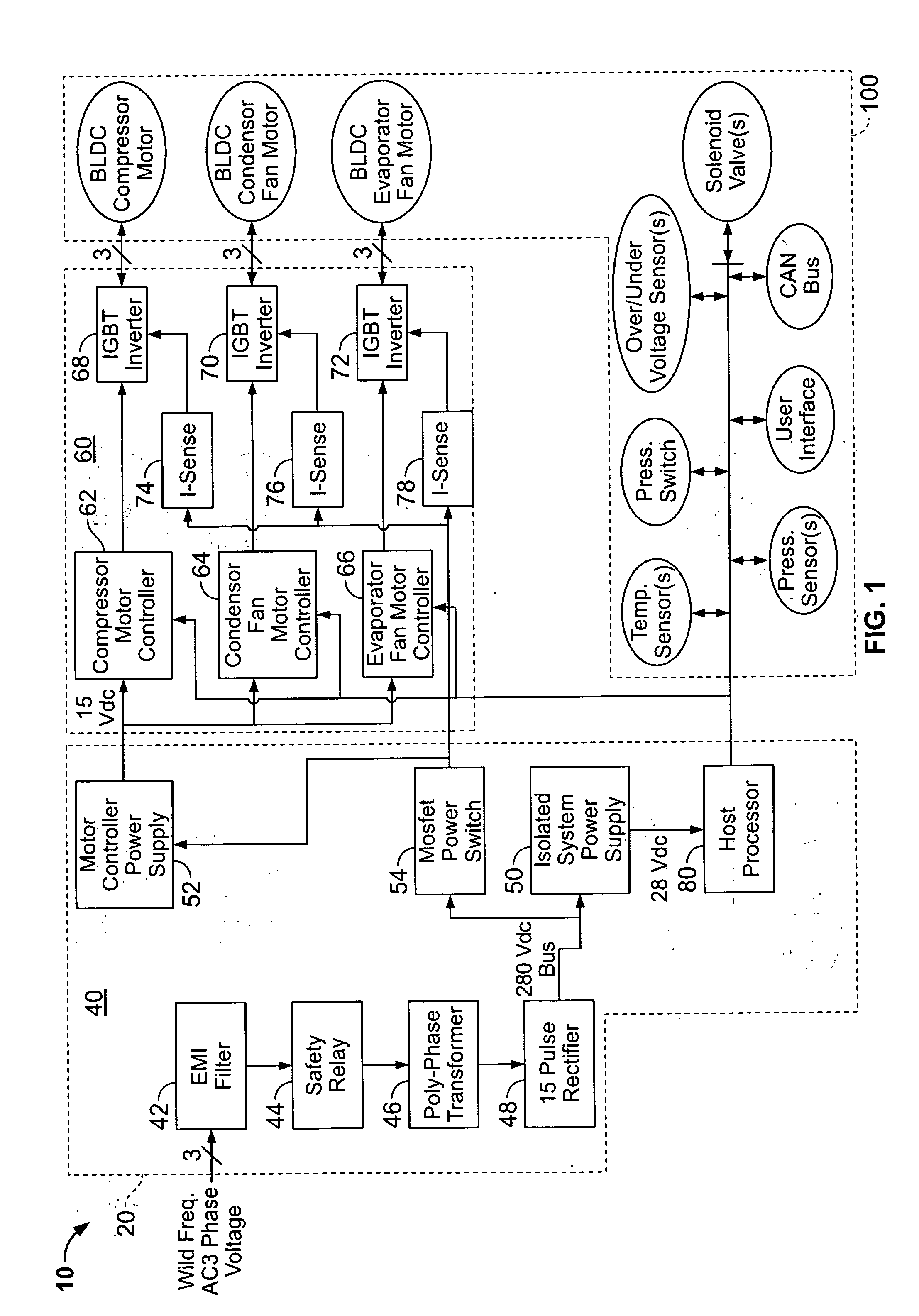
[0014]Referring now to the Figures, a wild frequency avionic refrigeration system and a controller therefor are provided. As shown in FIG. 1, an example wild frequency avionic refrigeration system 10 includes a controller 20 and a refrigeration line replaceable unit (LRU) 100 that is operated in closed-loop feedback control fashion by the controller 20. The controller 20 and refrigeration LRU 100 may communicate with each other via a wired (e.g., Ethernet cable, coaxial cable, twisted pair, etc.) or wireless (e.g., RF) connection. The controller 20, as shown, includes a power module 40, a motor control module 60 and a processing unit 80. Although the controller 20 is illustrated to be separate from the refrigeration LRU 100, the controller 20 and refrigeration LRU 100 may alternatively be integral or otherwise unitary. Additionally, although the example controller 20 is illustrated as including the power module 40, the motor control module 60 and the processing unit 80, one or more ...


PUM


Abstract

A wild frequency avionic refrigeration system and a controller therefore are provided. One embodiment of the refrigeration system includes: a refrigeration LRU including a vapor cycle system with a brushless DC compressor motor, a brushless DC condenser motor, a brushless DC evaporator motor and a plurality of sensors configured to output operating parameter data relative to the vapor cycle system; a power module configured to convert a wild frequency AC input voltage to at least one DC output voltage; a motor control module in communication with the brushless DC compressor, condenser and evaporator motors; and a processing module in communication with the plurality of sensors and the motor control module, wherein the processing module, according to the operating parameter data, outputs control signals to the motor control module for independently driving the brushless DC compressor, condenser and evaporator motors.

Description

FIELD OF THE INVENTION[0001]This invention pertains generally to refrigeration systems and more particularly to a wild frequency avionic refrigeration system.BACKGROUND OF THE INVENTION[0002]Conventional avionic refrigeration systems typically include a refrigeration line replaceable unit (LRU), for example, a chiller that is configured to keep items such as food and beverages cold. Such conventional avionic refrigeration systems have a number of drawbacks, largely stemming from the construction of the refrigeration LRU. As is known, conventional refrigeration LRUs include AC induction motors for operating the compressor, condenser and evaporator units. While AC induction motors are used for many applications due to their low cost and ruggedness, AC induction motors are not well suited to avionic applications due to their large size, weight and difficulty to accurately and variably control.[0003]For example, feedback control of AC induction motors is typically accomplished using ele...

Claims


Application Information

Patent Timeline
Patent Type & Authority Applications(United States)
IPC IPC(8): B60H1/32
CPCB60H1/00428F25B49/025F25B2600/112F25B2600/111F25B2600/025Y10S62/05Y02T10/88
Inventor RIZZO, RICHARD
Owner BE AEROSPACE INCORPORATED
Why Eureka
Try Eureka