Narrow-band laser device for exposure apparatus

Active Publication Date: 2008-05-22
USHIO DENKI KK +1
View PDF4 Cites 14 Cited by
  • Summary
  • Abstract
  • Description
  • Claims
  • Application Information

AI Technical Summary

Benefits of technology

[0032](1) The laser light beam shifts inside the ring resonator in each round trip, which allows as a result expanding the beam width.
[0033]This reduces in consequence the energy density of the laser light in the optical elements (OC, laser windows and high reflection mirrors) of the ring resonator of the amplification stage laser (PO). The life of the optical elements of the amplification stage laser (PO) is

Problems solved by technology

To achieve high outputs such as 90 W, the load on the chamber window of the amplifier (PA) or, the optical elements (in particular, chamber windows and OC) of the amplification stage laser (PO), increases, which is problematic in terms of the life of these optical elements.
In particular, the partial reflection (PR) film that coats the OC 24 of t

Method used


Image

  • Narrow-band laser device for exposure apparatus
  • Narrow-band laser device for exposure apparatus
  • Narrow-band laser device for exposure apparatus

Examples


first embodiment

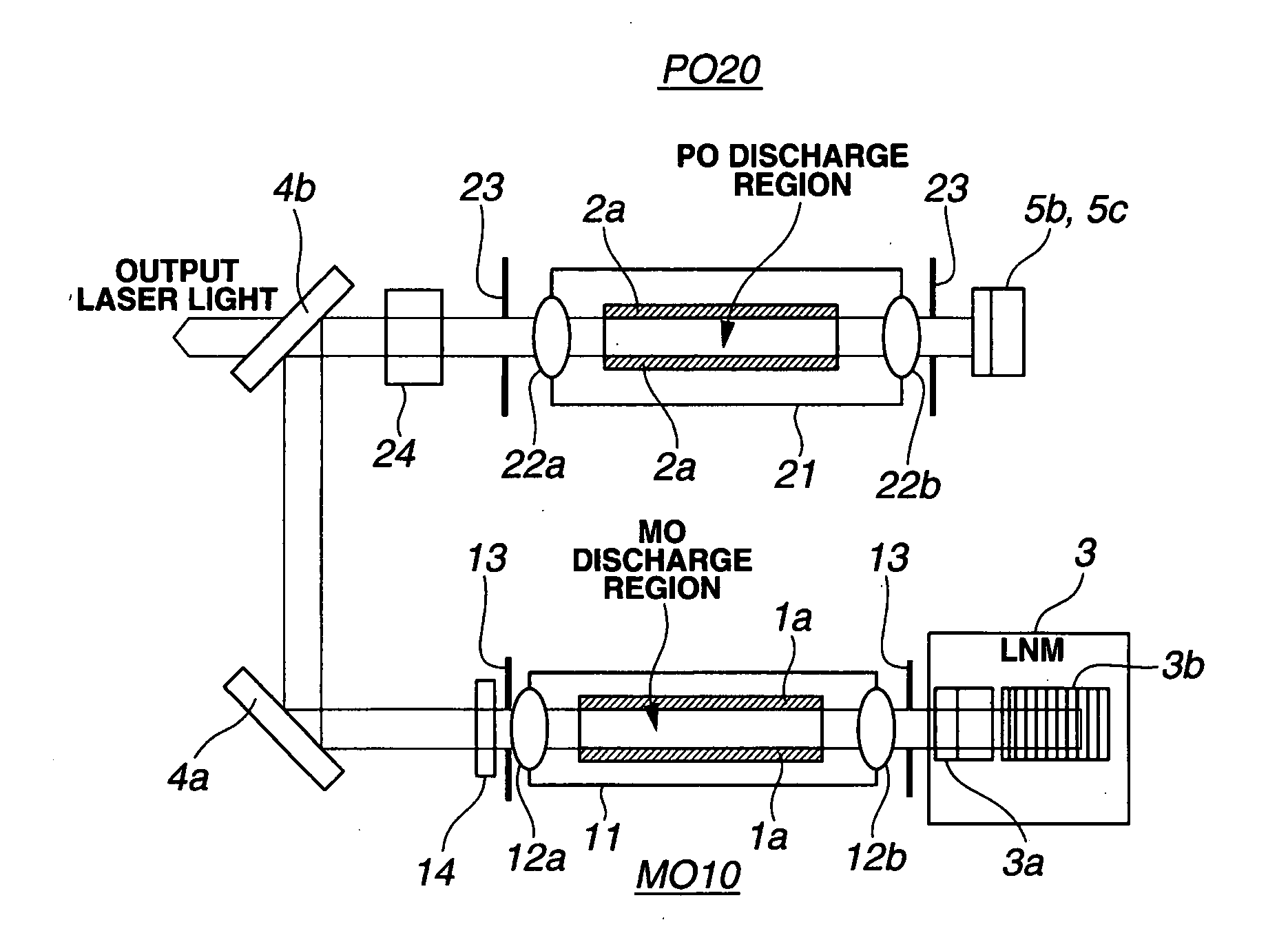
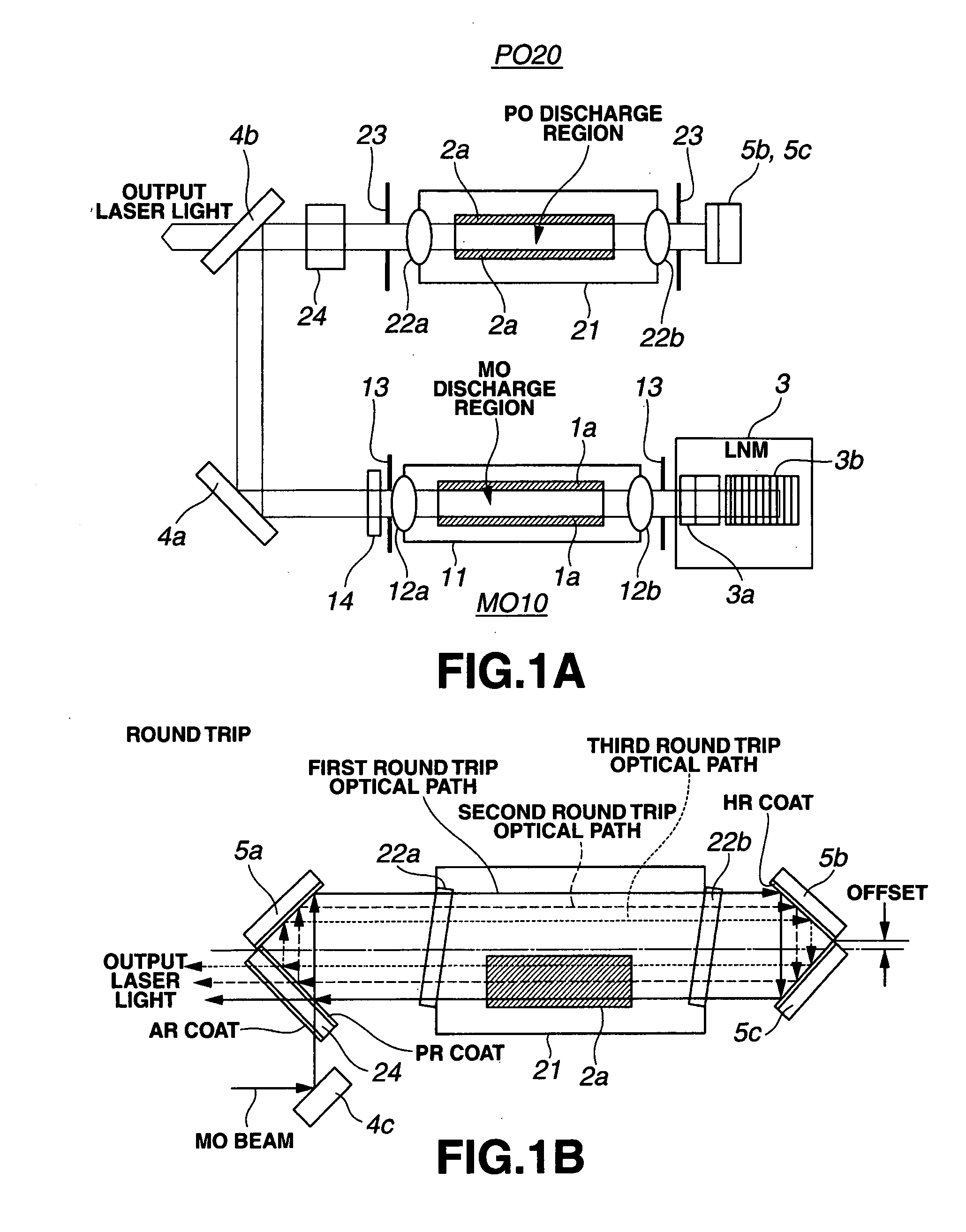
[0047]FIGS. 1A and 1B illustrate the configuration of a narrow-band laser device for exposure apparatus in the present invention, in an instance where a rectangular ring resonator is arranged in an amplification stage laser 20 (PO). FIG. 1A is a side-view of the amplification stage laser (PO) 20, while FIG. 1B is a top-side view of the same.

[0048]The configuration illustrated in FIG. 1A is identical to that illustrated in FIGS. 10A and 10B. Herein a laser beam emitted by an oscillation stage laser (MO) 10 functions as a seed laser beam, while the amplification stage laser (PO) 20 has a function of amplifying that seed laser light. The oscillation stage laser (MO) 10 and the amplification stage laser (PO) 20 have each respective laser chambers 11, 21, the interior whereof is filled with a laser gas. Inside each laser chamber there is arranged a pair of opposing electrodes 1a, 2a separated by a predetermined distance, such that discharge is effected through application of high-voltage...

second embodiment

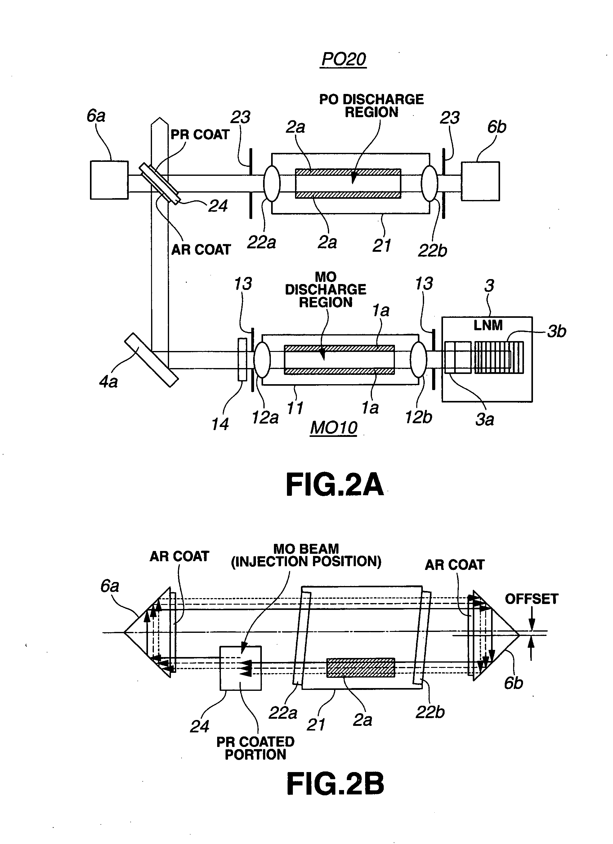
[0105]In the above embodiment an instance has been explained wherein mirrors are used in the resonator so that laser light is returned to a laser chamber by two high reflection mirrors. However, the same effect can be achieved if the laser beam is returned using total reflection prisms, such as those of the second embodiment, on the basis of Fresnel reflection at an angle somewhat smaller (several mrad) than 45 degrees.

fourth embodiment

[0106]FIG. 4 illustrates the configuration of a narrow-band laser device for exposure apparatus in the present invention, showing an instance where the axis of one mirror in the rectangular ring resonator of FIG. 1 is displaced.

[0107]The figure illustrates a top view of an amplification stage laser (PO) 20. The configuration and the like of an oscillation stage laser (MO) are omitted herein, being identical to that of FIG. 1. That is, a laser beam emitted by an oscillation stage laser (MO) 10 functions as a seed laser beam, while an amplification stage laser (PO) 20 has a function of amplifying that seed laser light. The oscillation stage laser (MO) 10 and the amplification stage laser (PO) 20 have each respective laser chambers 11, 21, the interior whereof is filled with a laser gas. Inside each laser chamber there is arranged a pair of opposing electrodes 1a, 2a separated by a predetermined distance, such that discharge is effected through application of high-voltage pulses to the...


PUM


Abstract

A narrow-band laser device for exposure apparatus that allows to reduce damage to, and to hence extend the life of, optical elements such as chamber windows, output coupling mirrors or the like. A ring resonator is provided in an amplification stage laser of the narrow-band laser device for exposure apparatus that comprises an oscillation stage laser and an amplification stage laser. An OC, a high reflection mirror and a high reflection mirror are arranged to be offset, for instance, relative to a longitudinal direction axis of discharge electrodes. As a result, the beam width of laser light injected through the OC of the amplification stage laser becomes wider as the beam shifts inside the ring resonator, in each round trip within the ring resonator. The energy density of laser light in the optical elements of the amplification stage laser becomes reduced thereby, thus prolonging the life of the optical elements.

Description

BACKGROUND OF THE INVENTION[0001]1. Field of the Invention[0002]The present invention relates to an injection-locked discharge excited laser device for exposure apparatus, comprising a narrow-band laser oscillation stage laser and an amplification stage laser, and more particularly to a laser device for exposure apparatus that allows to extend the life of optical elements such as chamber windows, output coupling mirrors (OC) and the like.[0003]2. Description of the Related Art[0004]Excimer lasers are being used in recent years as light sources for semiconductor exposure devices. In particular, ArF laser light sources having high outputs (40 W or more) and ultra-narrow bands (0.2 pm or less) are being used in the technology node (not more than 45-nm).[0005]With a view to securing high dose stability and achieving higher throughputs, yet higher outputs, of 90 W or more, are being required of ArF laser light sources in light sources for exposure devices.[0006]To meet the above demands ...

Claims


Application Information

Patent Timeline
IPC IPC(8): H01S3/134H01S3/14H01S3/083
CPCH01S3/005H01S3/2325H01S3/2251
Inventor WAKABAYASHI, OSAMU
Owner USHIO DENKI KK
Why Eureka
Try Eureka