
Crowd counting and monitoring

Active Publication Date: 2008-05-22
RGT UNIV OF MINNESOTA
View PDF6 Cites 133 Cited by
  • Summary
  • Abstract
  • Description
  • Claims
  • Application Information

AI Technical Summary

Benefits of technology

[0154]To improve robustness and stability, an example of the present subject matter uses extensions to a Kalman filter tracker based on the history of estimates. Various methods, such as those based on a heuristic training or based on shape models, can be used for estimating crowd size. Motion trajectories of these crowds can be generated for further data analysis. The system can be configured to count and track people in the presence of occlusions, group merges, and splits. The system is substantially view-point invariant as it uses data from camera calibration methods.Additional Examples
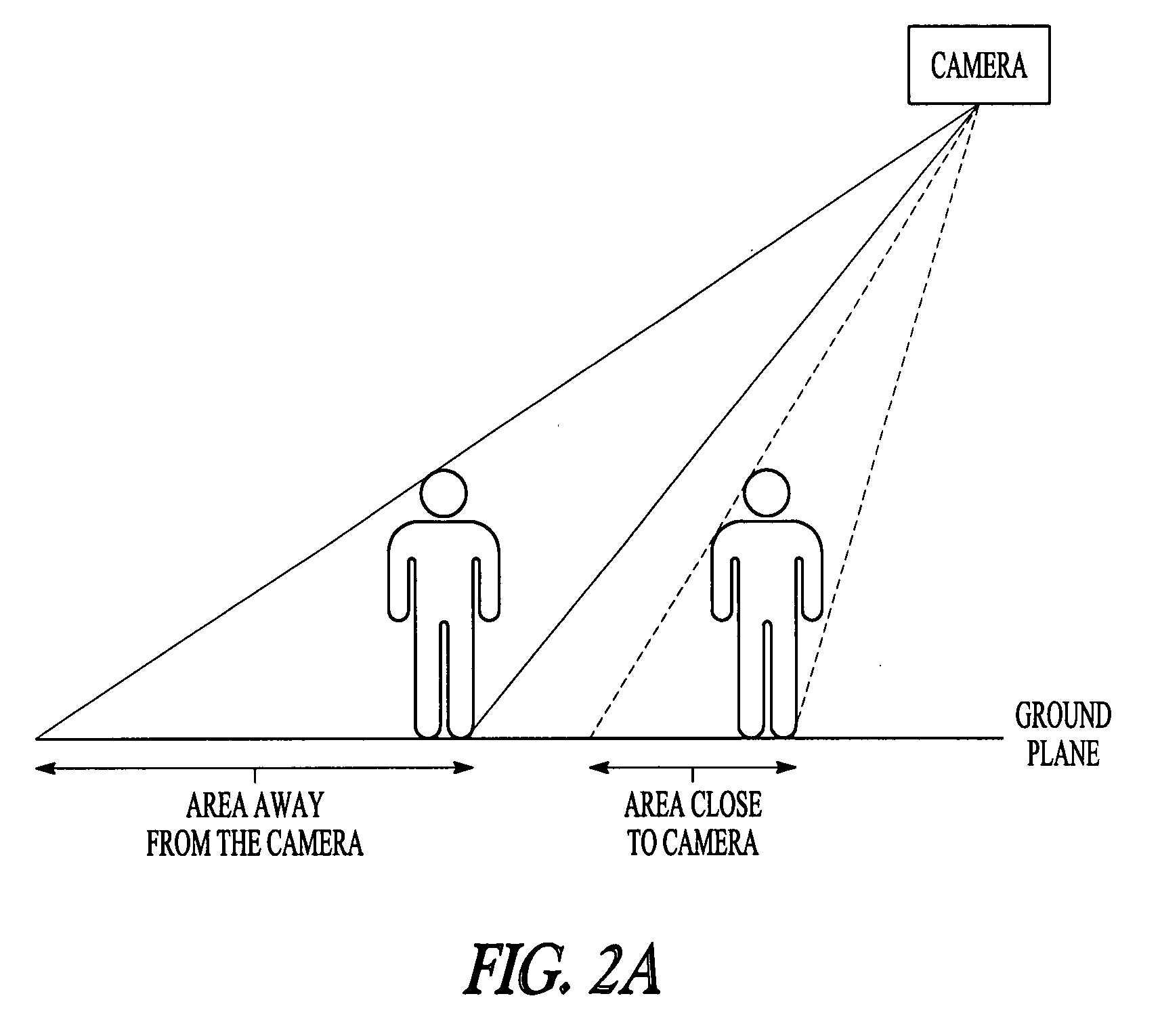
[0160]In one example, data derived from regions near the horizon is discarded in calculating count or tracking information. Other methods can also be used to mitigate errors from such data.

Problems solved by technology

Determining the number of members in a crowd is a difficult problem.
Manual methods are exceedingly costly and are generally too slow.
Previous attempts to use a processor have suffered from scalability and accuracy problems.
The Kalman filter tracker alone does not provide information about the number of people in the group.
It may be insufficient to estimate the count independently frame-wise since such a method is not robust to unusual situations which may occur temporarily.
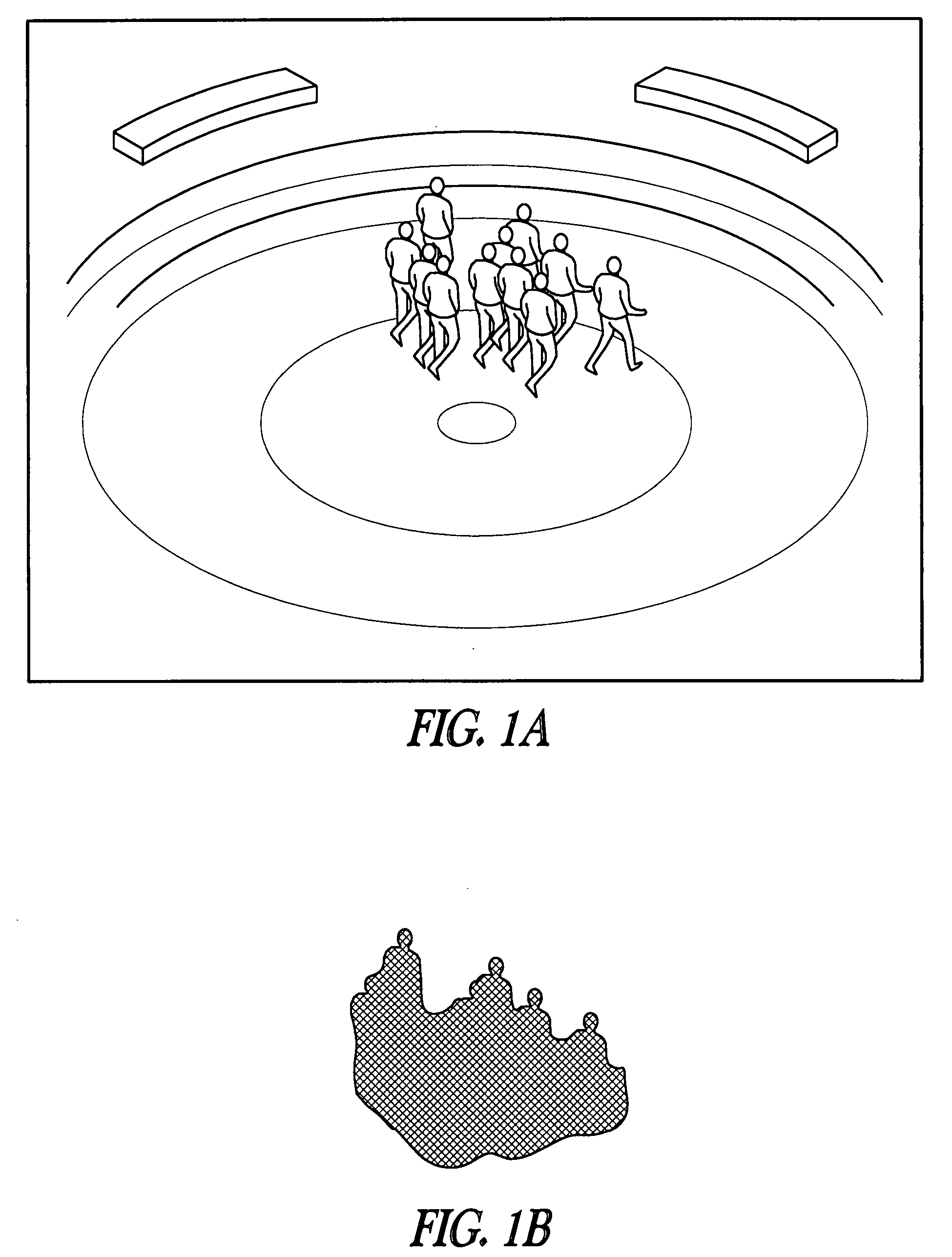
Since the shape of the blob does not represent a single group, the assumptions about the shape of the group do not hold true.
The heuristic-based method may not be suitable for all situations.
For example, the heuristic-based method assumes a high spatial density which may not be suitable for sparse groups.
The accuracy may be affected if the groups include very tall or very short members.
The heuristic-based method may not handle changes in the configuration or the dynamics of the group explicitly.
If a single ellipse is selected to approximate this configuration, the result may be a poor fit, as shown in FIG. 5B.
The merged condition is typically temporary and while merged, a shape-based estimate may not be valid due to the different directions of motion of the people involved.
The ellipse fitting method may be vulnerable to this error as reflected in the tables.
As the distance from the camera increases, the per pixel error increases, (i.e., the distance between two neighboring pixels is greater).

Method used


Image

  • Crowd counting and monitoring
  • Crowd counting and monitoring
  • Crowd counting and monitoring

Examples


Embodiment Construction

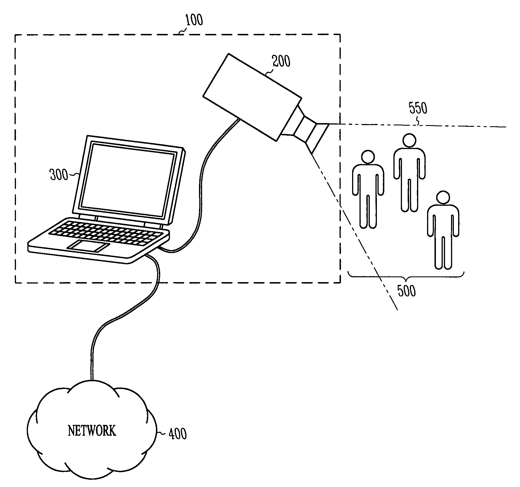
[0017]The following detailed description includes references to the accompanying drawings, which form a part of the detailed description. The drawings show, by way of illustration, specific embodiments in which the present subject matter may be practiced. These embodiments, which are also referred to herein as “examples,” are described in enough detail to enable those skilled in the art to practice the present subject matter. The embodiments may be combined, other embodiments may be utilized, or structural, logical and electrical changes may be made without departing from the scope of the present subject matter. The following detailed description is, therefore, not to be taken in a limiting sense, and the scope of the present subject matter is defined by the appended claims and their equivalents.

[0018]In this document, the terms “a” or “an” are used, as is common in patent documents, to include one or more than one. In this document, the term “or” is used to refer to a nonexclusive ...


PUM


Abstract

This document discusses, among other things, methods and systems for determining the number of members in a group as well as changes over a period of time. Using an image of the scene, an overlap area is calculated by projecting portions of the image onto spaced apart and parallel planes. A filter correlates the overlap area to the number of members.

Description

STATEMENT OF GOVERNMENT RIGHTS[0001]The invention was made with Government support under agency grant number IIS-0219863 awarded by the National Science Foundation. The Government has certain rights in this invention.TECHNICAL FIELD[0002]This document pertains generally to image processing, and more particularly, but not by way of limitation, to crowd counting and monitoring.BACKGROUND[0003]In traffic control, accurate data as to pedestrian and crowd tracking can be used to improve safety and traffic flow. For example, a light-controlled intersection can be configured to operate automatically depending on the number of pedestrians waiting to cross a roadway.[0004]Determining the number of members in a crowd is a difficult problem. Manual methods are exceedingly costly and are generally too slow. Previous attempts to use a processor have suffered from scalability and accuracy problems.BRIEF DESCRIPTION OF THE DRAWINGS[0005]In the drawings, which are not necessarily drawn to scale, li...

Claims


Application Information

Patent Timeline
IPC IPC(8): G06K9/00
CPCG06M11/00G06K9/00362G06V40/10
Inventor KILAMBI, PRAHLADMASOUD, OSAMA T.PAPANIKOLOPOULOS, NIKOLAOS
Owner RGT UNIV OF MINNESOTA
Learn More