Bicondylar knee resurfacing prosthesis

a bicondylar and knee technology, applied in the field of bicondylar knee resurfacing prosthesis, can solve the problems of undue pain in the immediate post operative period, extensive soft tissue disruption, irreparable scarring of major anatomical structures,

Active Publication Date: 2008-05-22
TERMANINI ZAFER
View PDF5 Cites 14 Cited by
  • Summary
  • Abstract
  • Description
  • Claims
  • Application Information

AI Technical Summary

Benefits of technology

[0013]In view of the foregoing disadvantages inherent in the known types of knee resurfacing prosthesis now present in the prior art, the present invention provides a new bicondylar knee resurfacing prosthesis const

Problems solved by technology

However, unicondylar prostheses in general present a high rate of failure due to loosening and dislocation secondary to poor distribution of weight and high concentration of stress over a small surface.
The main problem with conventional knee resurfacing prostheses is the fact that the surgical approach used during their insertion causes extensive soft tissue disruption and irreparable scarring to major anatomical structures.
Another problem with conventional knee resurfacing prostheses is the anterior surgical approach that violates the extensor mechanism of the knee joint namely the quadriceps muscle, quadriceps tendon and the extensor retinaculum.
Another problem with conventional knee resurfacing prostheses is the need to laterally dislocate and “flip” over the patella and the patellar tendon in order to access both condyles, which frequently weakens the insertion of the patellar tendon, causing undue pain in

Method used


Image

  • Bicondylar knee resurfacing prosthesis
  • Bicondylar knee resurfacing prosthesis
  • Bicondylar knee resurfacing prosthesis

Examples


Embodiment Construction

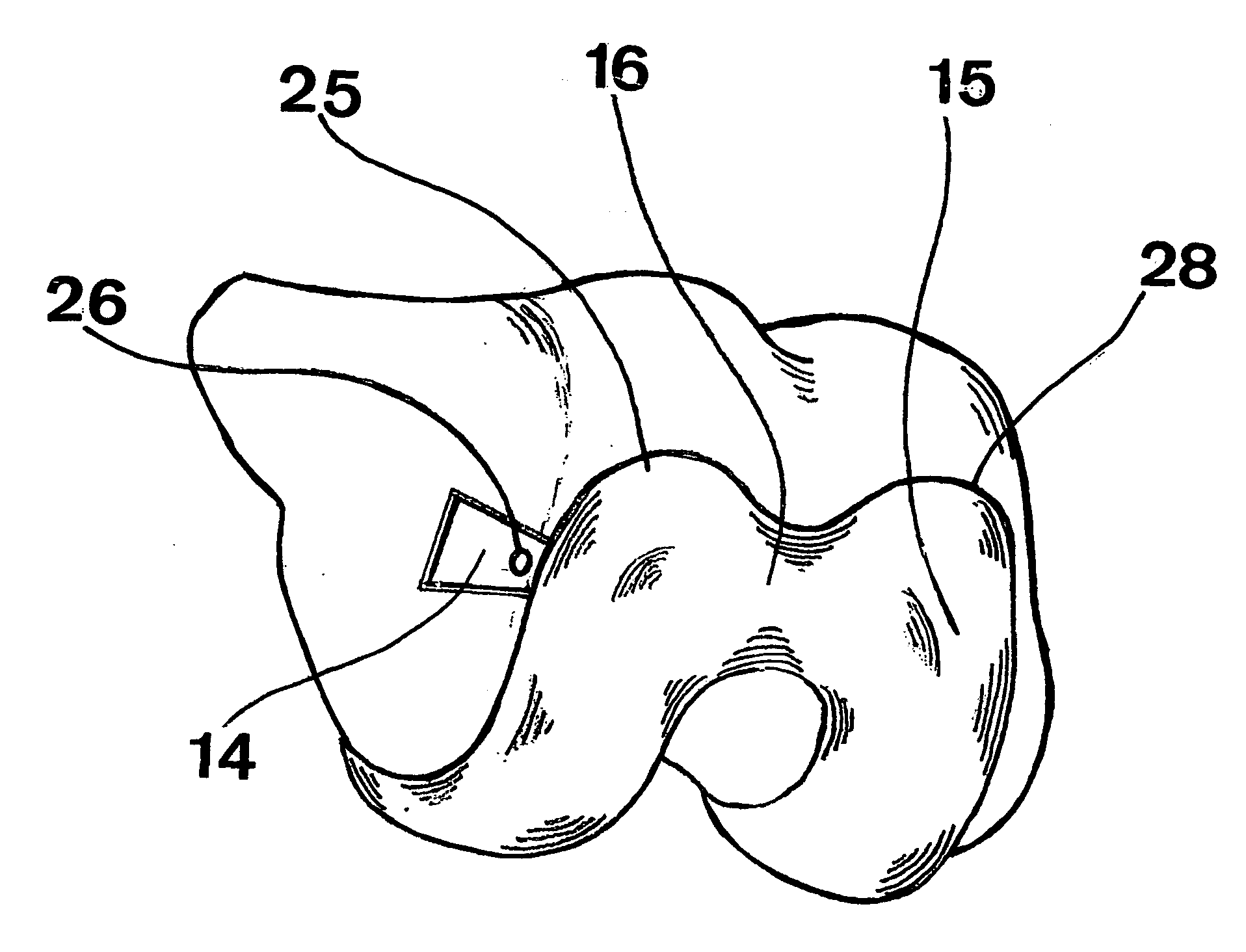
[0036]Turning now descriptively to the drawings, in which similar reference characters denote similar elements throughout the several views, the attached figures illustrate a concise bicondylar knee resurfacing prosthesis, which comprises a thin metallic femoral arcuate component, a metallic tibial tray and a polyethylene tibial insert.

[0037]An arcuate metallic femoral component having a polished convex articular surface in a form of two condyles, medial 28 and lateral 25 that are connected with an intercondylar bridge 16.

[0038]The preferred embodiment of the present invention is a concise thin shell like bicondylar metallic arcuate component having a thickness between 2 millimeters at its thinner posterior condylar region 18 and 6 millimeters at the thickest weight bearing portion 17.

[0039]The concave surface having a metallic transverse ridge 14. Said ridge has the shape of a dovetail in its section and extend along the entire width of the femoral component, as depicted in FIG. 4....


PUM


Abstract

A bicondylar knee resurfacing prosthesis for limited knee resurfacing procedure inserted through a direct mini lateral approach, which avoid disruption of the extensor mechanism or damage to the quadriceps tendon. The inventive device includes a reduced femoral component, a metallic tibial tray and a polyethylene tibial insert.
A metallic reduced femoral component having a thin polished convex articular surface in a form of two condyles, medial and lateral, connected with an intercondylar bridge. The concave surface having a metallic dovetail transverse ridge across the entire width of the femoral component precisely positioned at the level of maximum weight bearing contact in full extension. The concave surface provides fine asperities and voids to allow bone ingrowth or can be cemented using conventional methyl methacrylate bone cement.
The tibial tray provides a dovetail recess along the superior surface and transversely across its entire width, which will slidingly receive the polyethylene tibial insert. The bottom surface of the metallic tibial tray in contact with the tibial plateau has a dovetail ridge, which extends transversely along the entire width of the tibial component securing the tibial component to the resected tibial plateau.
The tibial insert is made of polyethylene and has the same shape and size of the tibial metallic tray. It provides a dovetail that matches the one on the tibial tray so it can be easily driven in and locked in place. The surface of the tray provides two shallow condylar grooves that conformably match the condylar convex surfaces of the metallic femoral component.

Description

CROSS-REFERENCE TO RELATED APPLICATIONS[0001]This application claims priority from prior U.S. Provisional Application No. 60 / 860,409 filed Nov. 21, 2006. The entire disclosure of which is incorporated herein by reference.BACKGROUND OF THE INVENTION[0002]1. Field of the Invention[0003]The present invention relates generally to knee resurfacing prosthesis and more specifically it relates to a bicondylar knee resurfacing prosthesis for bicompartmental knee resurfacing, which is inserted through a limited and minimally invasive lateral approach, without any disruption of the extensor mechanism or damage to the quadriceps tendon.[0004]2. Description of the Related Art[0005]It can be appreciated that knee-resurfacing prostheses have been in use for years to treat articular surfaces destroyed by arthritis or pathological processes secondary to trauma. Basically, the natural knee joint comprises an upper femoral articular surface having two condylar surfaces and a lower tibial plateau compr...

Claims


Application Information

Patent Timeline
IPC IPC(8): A61F2/38
CPCA61F2/38A61F2/3859A61F2/389A61F2220/0025A61F2002/30883A61F2002/4635A61F2002/30387
Inventor TERMANINI, ZAFER
Owner TERMANINI ZAFER
Why Eureka
Try Eureka