
Modular Garment

a technology of modular garments and garment sleeves, applied in the direction of details of portable computers, nuclear elements, snap fasteners, etc., can solve the problem that it is not feasible to wear it together with an electronic garment, and achieve the effect of improving user comfor

Inactive Publication Date: 2008-05-29
SAGEM DEFENSE SECURITE SA
View PDF13 Cites 19 Cited by
  • Summary
  • Abstract
  • Description
  • Claims
  • Application Information

AI Technical Summary

Benefits of technology

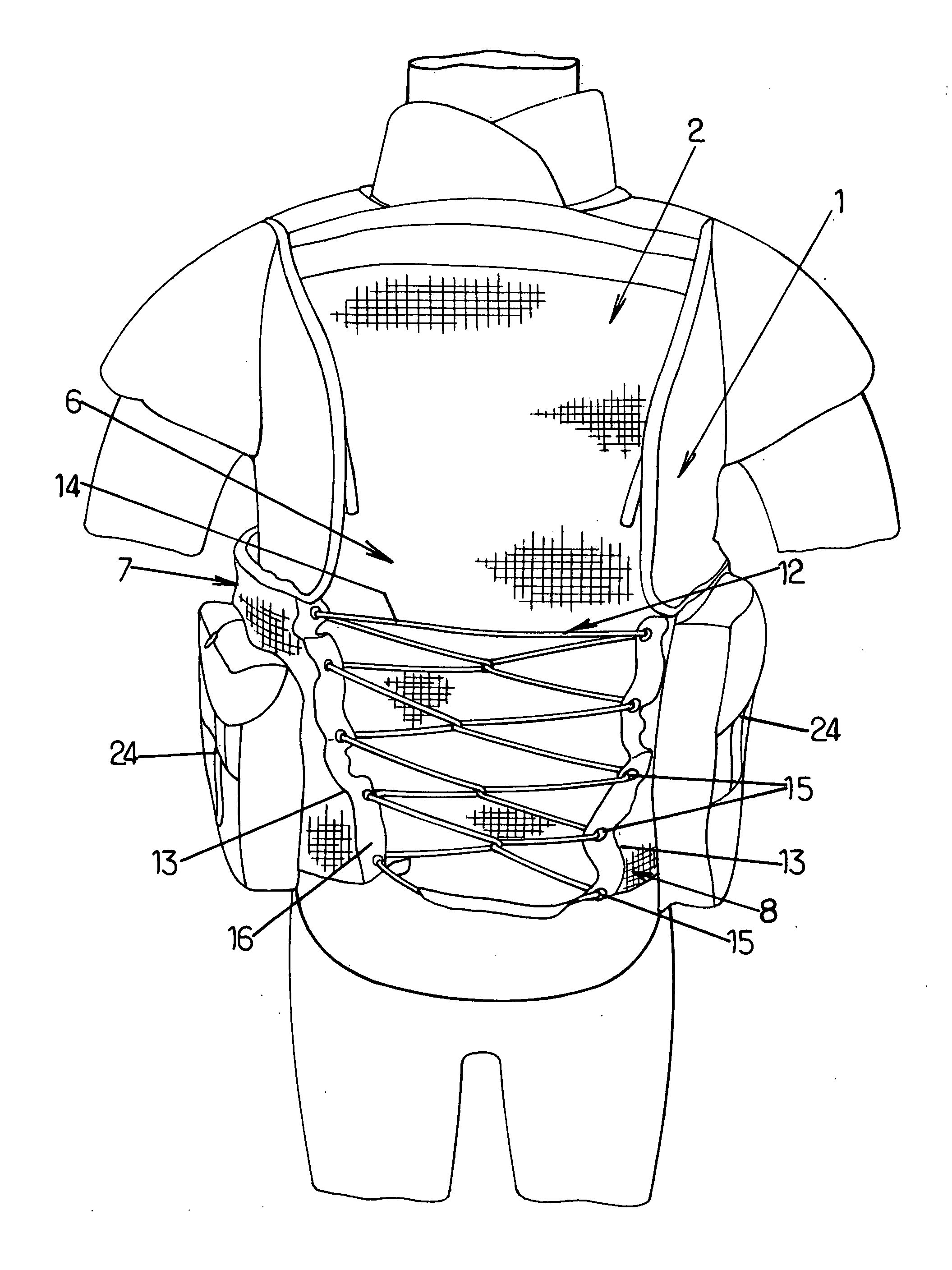
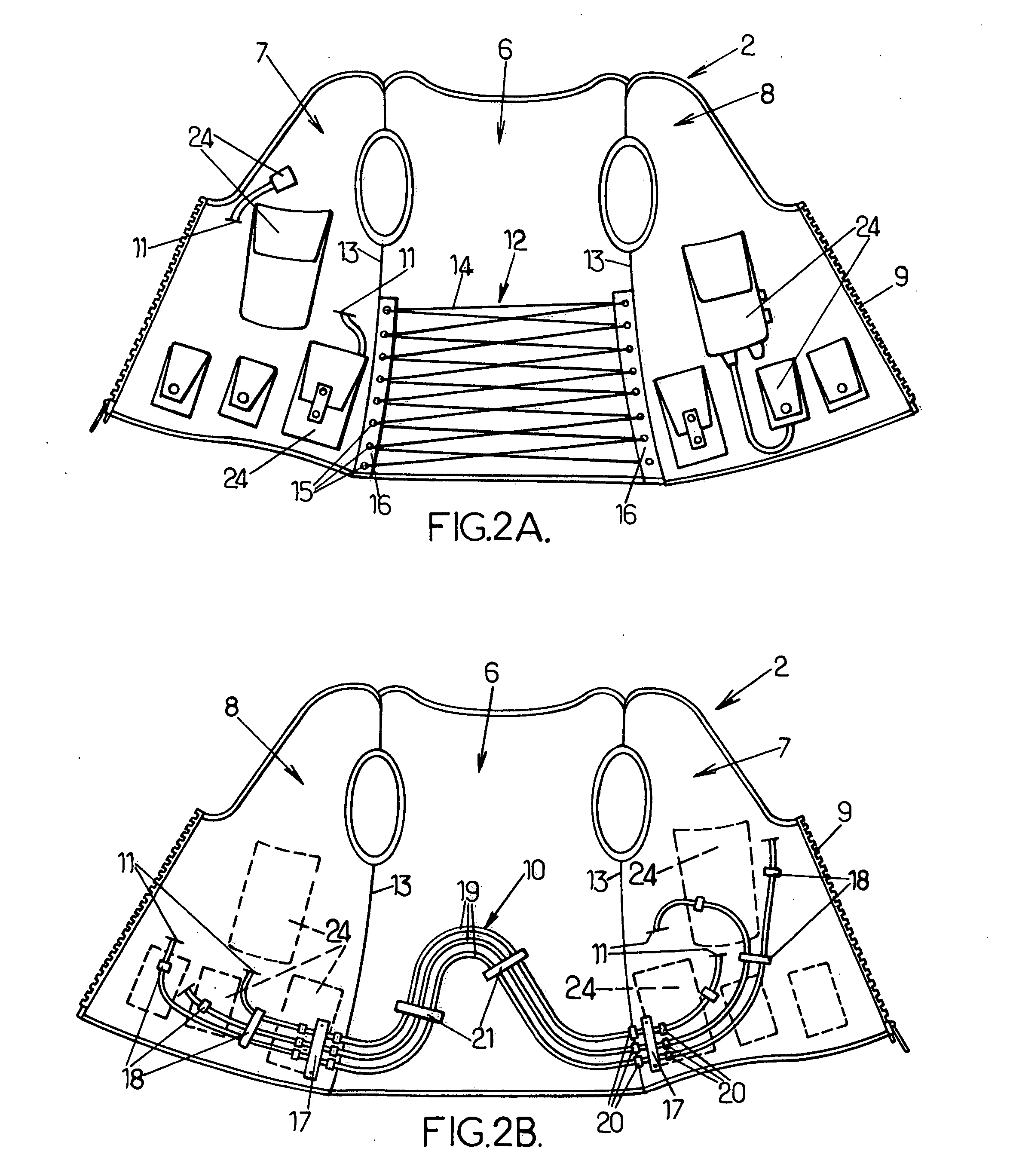
[0013]at least one electrical cable running across the inside face of said electronic garment between at least said two electrical devices, said cable being attached to said side parts of said electronic garment and not being attached to said central part of said electronic garment in front of which it runs freely along a curved path enabling it to adapt to changes in the width of said central part arising from the different ways in which said electronic garment can be worn.
[0014]The modular garment arranged in accordance with the invention simultaneously meets all the requirements that occur in practice because the width adjustability provided by the central part enables the electronic garment to adapt to being worn directly or worn over the protective garment. The two functions of protection and carrying equipment can thus be separated and the protective garment need only be worn when necessary, thus improving user comfort especially in hot and / or humid environments. Moreover, this same adjustability means that in both configurations the electronic garment can be adjusted to closely fit the torso of the user so that the equipment is held securely and cannot shake about and make a noise. The fact that when the protective garment is required, the electronic garment is worn on top of it, leaves direct and immediate access to the electronic and / or computational devices, which is what users want.
[0016]In practice, several cables will typically be provided for all the necessary interconnections and at least the two attachment means are therefore shaped to hold the cables side by side in a flat harness at least in front of the central part of the garment, in order to prevent the cables from lying on top of each other and becoming uncomfortable for the user. The attachment means may be of any appropriate design, so for example they may be flat clamps suitable for the largest-diameter cable; such an arrangement offers the further advantage of allowing axial relative movements by the smaller-diameter cables and therefore not making the garment too stiff. However, it is advantageous to provide stop means on the cables on either side of the respective attachment means in such a way as to limit the amplitude of the axial relative movements of the cables. It is also desirable that, between the two abovementioned cable attachment means, in front of the central part of the garment, there should be at least one unattached assembly member, not attached to the garment, to help keep the cables side by side in a flat harness.
[0018]To facilitate the use of the electronic garment and ensure that cables do not become snagged when the garment is being put on, for example, it is desirable that the central part of the garment comprise a flexible lining (e.g. in the form of an open-mesh fabric) covering the cable or cables.

Problems solved by technology

However, the electrical and / or computational interconnection of equipment distributed in differing locations on the garment is a problem with this type of garment.
Wearing a protective garment of this kind is a serious problem because it is usually thick and relatively inflexible, so that at first sight it would not seem feasible to wear it together with an electronic garment.

Method used


Image

  • Modular Garment
  • Modular Garment
  • Modular Garment

Examples


Embodiment Construction

[0027]In the description which follows, the invention will be described more specifically in its application to the armed forces and armed police, which is a preferred application even if it is not an exclusive one.

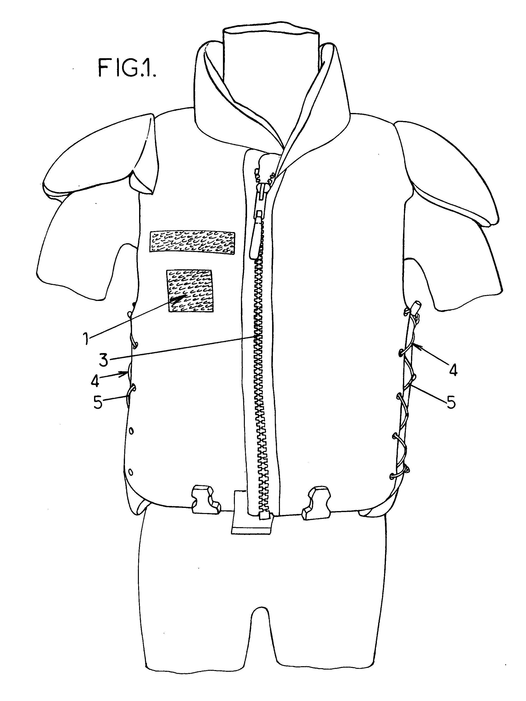
[0028]To achieve the objects set out above, the invention provides a modular garment comprising a first garment or protective garment, hereinafter denoted as a whole by the reference number 1, and a second garment or electronic garment, hereinafter denoted as a whole by the reference number 2.

[0029]Referring initially to FIG. 1, this shows an example of a first garment or protective garment denoted as a whole by the reference 1 (the drawing shows a ballistics vest for protection against handguns and edged weapons, although in other applications it could be a thermal garment giving protection against cold or heat). Such a garment is thick and relatively inflexible; in the case of the ballistics vest, it is hot, which is a real problem in hot environments. Such a garment is...


PUM


Abstract

Modular garment comprising: a thick and relatively inflexible protective first garment, intended for optional wear; and an electronic garment having a flexible central part at the back and two side parts; the width of the central part is adjustable so that it can be made narrow or wide (depending on whether the electronic garment is worn on its own or over the first garment); several electrical and / or electronic devices are supported by the side parts; and at least one electrical cable runs across the inside face of the electronic garment between the electrical devices, this cable being attached to the side parts without being attached to the central part in front of which it runs freely along a curved path so as to be able to adapt to the modifications in the width of the central part.

Description

BRIEF DESCRIPTION OF THE INVENTION[0001]The present invention relates in a general way to the field of specialized garments for certain professionals.BACKGROUND OF THE INVENTION[0002]In the exercise of their functions, certain professionals need electronic and / or computational equipment which, together with the corresponding electrical power supply (the battery), they have to wear, preferably in such a way as to leave their hands free. It is known in the prior art to place this equipment in bags or pouches fixed removably to predetermined locations on the garment, but also to provide the garment with multiple pockets suitable for holding the various items, these bags and / or pockets being arranged at various positions on the garment in such a way that the weight of the equipment is distributed and thus easier to carry. Various different forms of specialized garment designed for this purpose are known: see for example documents U.S. Pat. No. 5,831,198, U.S. Pat. No. 5,265,782; also, d...

Claims


Application Information

Patent Timeline
IPC IPC(8): A41D1/04F41H1/02A41D1/00
CPCA41D1/005A41D13/0012Y10T24/21F41H1/02G06F1/163A41D2300/33
Inventor RENE, FREDERICBRUCKER, XAVIER
Owner SAGEM DEFENSE SECURITE SA
Learn More