System and method for a charged particle beam

a technology of charged particles and beams, applied in the direction of discharge tubes/lamp details, magnetic discharge control, instruments, etc., can solve the problems of low landing energy, small spot size, and still a big challenge for high resolution, and achieve the effect of large scanning field

Active Publication Date: 2008-05-29
ASML NETHERLANDS BV
View PDF2 Cites 35 Cited by
  • Summary
  • Abstract
  • Description
  • Claims
  • Application Information

AI Technical Summary

Benefits of technology

[0015]An in-lens electrostatic deflector is located between the upper pole pieces and the shared pole piece of the conical magnetic lens and immersion magnetic lens to achieve large scanning field. The in-lens deflector can have the same voltage as the upper pole piece or the shared pole piece of the magnetic lens.

Problems solved by technology

However, it still is a big challenge for high resolution, low landing energy and small spot size for prior arts.

Method used


Image

  • System and method for a charged particle beam
  • System and method for a charged particle beam
  • System and method for a charged particle beam

Examples


Embodiment Construction

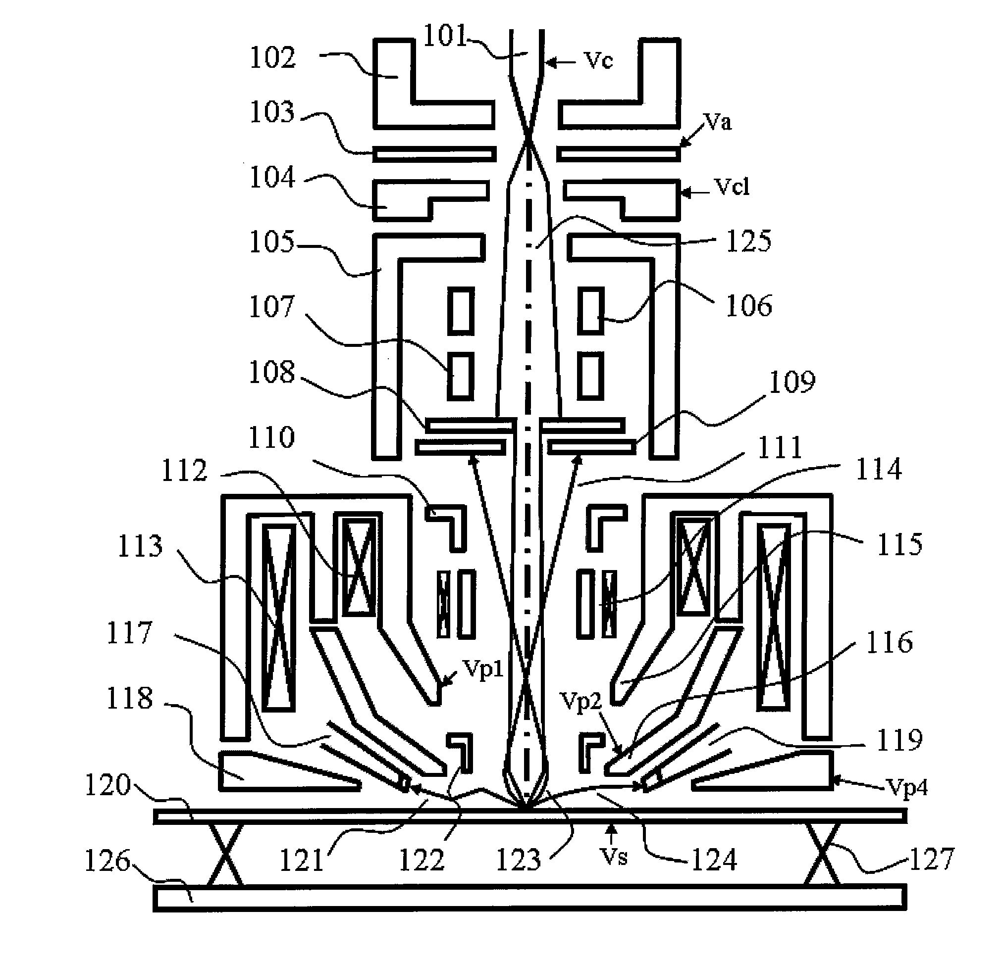
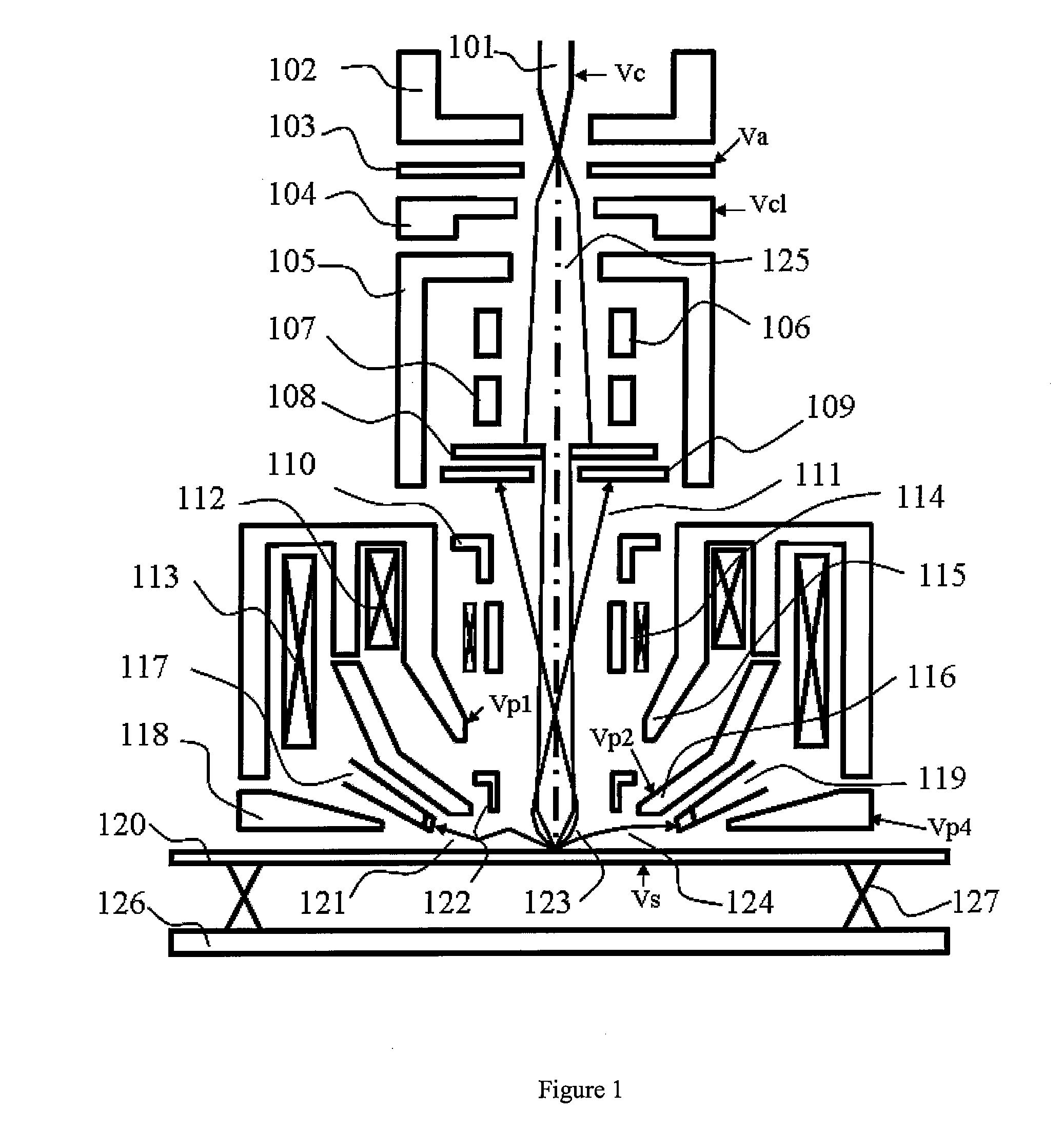
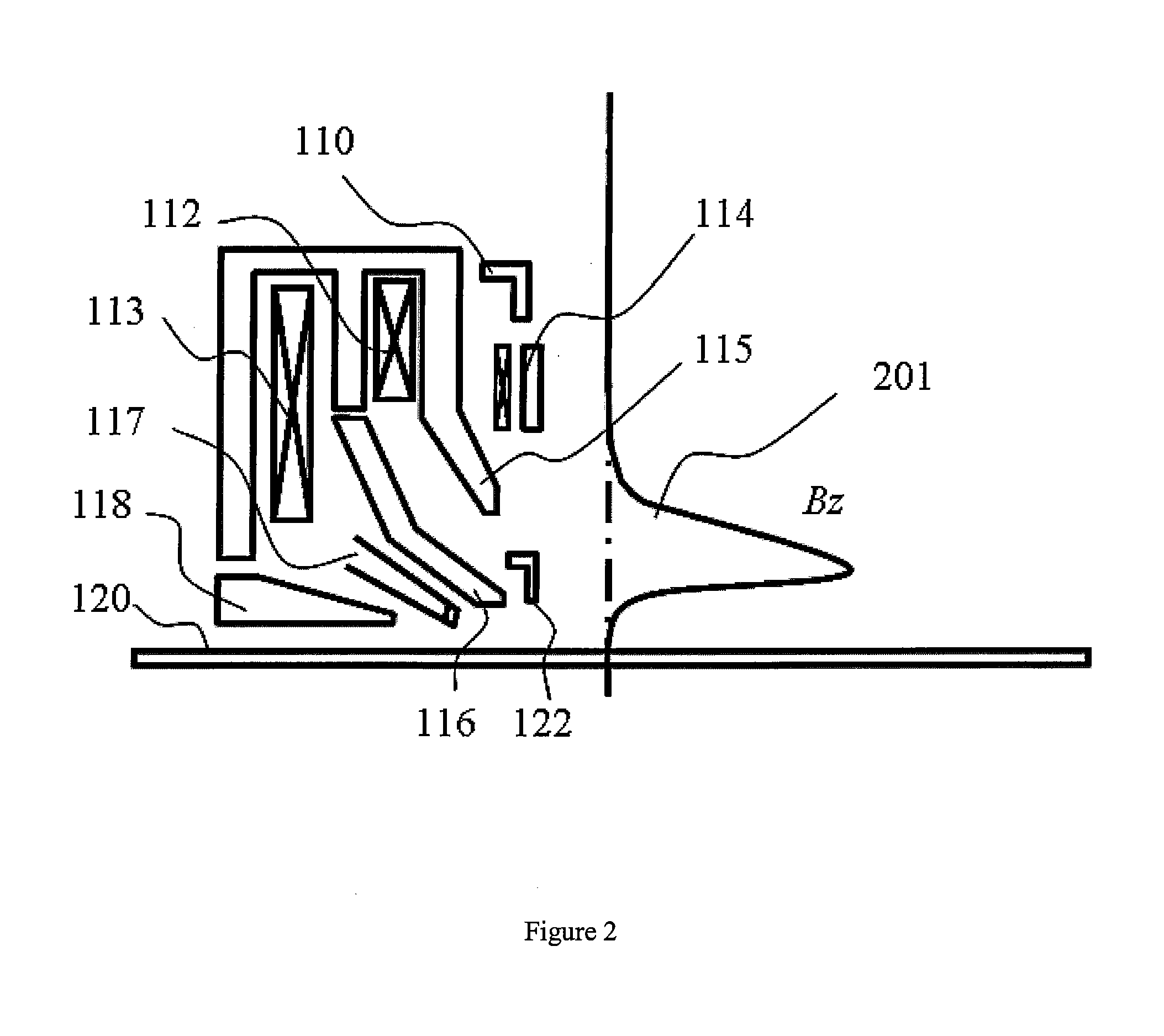
[0027]This invention relates to system and method for charged particle beam. More specifically, embodiments of the present invention provides a apparatus for generating and focusing primary charged particle beam onto a conductive or non-conductive specimen and collecting the released charged particles and / or X-ray from the specimen to form an image or a spectrum of the specimen. Merely by way of example, the present invention has been used to provide a low-landing scanning electron microscope, but it would be recognized that the invention has a much broader range of applicability.

[0028]As explained above, charged particle beam systems have a wide range of applications. For example, there are many reasons why low landing energy SEM is widely adopted in the semiconductor industry for inspection, defect review and CD measurement. For example, low landing energy charged particle beam causes less potential irradiation damage on the IC device. In addition, charging balance on the unfinish...


PUM


Abstract

System and method for charged particle beam. According an embodiment, the present invention provides a charged particle beam apparatus. The apparatus includes a charged particle source for generating a primary charged particle beam. The apparatus also includes at least one condenser lens for pre-focusing the primary charge particle beam. Furthermore, the apparatus includes a compound objective lens for forming the magnetic field and the electrostatic field to focus the primary charged particle beam onto a specimen in the charged particle beam path. The specimen includes a specimen surface. The compound objective lens includes a conical magnetic lens, an immersion magnetic lens, and an electrostatic lens, the conical magnetic lens including an upper pole piece, a shared pole piece being electrically insulated from the upper pole piece, and an excitation coil.

Description

CROSS-REFERENCES TO RELATED APPLICATIONS[0001]This application claims priority to U.S. Provisional Application No. 60 / 862,943, filed Oct. 25, 2006, which is incorporated herein by reference for all purposes.BACKGROUND OF THE INVENTION[0002]This invention relates to system and method for charged particle beam. More specifically, embodiments of the present invention provides a apparatus for generating and focusing primary charged particle beam onto a conductive or non-conductive specimen and collecting the released charged particles and / or X-ray from the specimen to form an image / or a spectrum of the specimen. Merely by way of example, the present invention has been used to provide a low-landing scanning electron microscope, but it would be recognized that the invention has a much broader range of applicability.[0003]The low landing energy and high resolution charged particle beam apparatus, (e.g. scanning electron microscope, or SEM) is an important metrology tool for inspection, rev...

Claims


Application Information

Patent Timeline
Patent Type & Authority Applications(United States)
IPC IPC(8): H01J1/50
CPCH01J37/145H01J37/28H01J2237/0475H01J2237/2807H01J2237/14H01J2237/24485H01J2237/12
Inventor LIU, XUEDONGZHANG, XUWANG, JOETSENG, EDWARDCHEN, ZHONGWEI
Owner ASML NETHERLANDS BV
Why Eureka
Try Eureka