

Rotor assembly and method of assembling a rotor of a high speed electric machine
a high-speed electric machine and rotor assembly technology, which is applied in the direction of stator/rotor body manufacturing, magnetic circuit rotating parts, magnetic circuit shape/form/construction, etc., can solve the problems of limiting the ability to disassemble the rotor from the shaft without damaging either the rotor or the shaft, and reducing the efficiency of such electric machines. , to achieve the effect of high power density and enhanced performan
- Summary
- Abstract
- Description
- Claims
- Application Information
AI Technical Summary
Benefits of technology
Problems solved by technology
Method used
Image

Examples
Embodiment Construction
[0038]The present invention will now be described more fully hereinafter with reference to the accompanying drawings, which illustrate embodiments of the invention. This invention may, however, be embodied in many different forms and should not be construed as limited to the illustrated embodiments set forth herein. Rather, these embodiments are provided so that this disclosure will be thorough and complete, and will fully convey the scope of the invention to those skilled in the art. Like numbers refer to like elements throughout. Prime notation, if used, indicates similar elements in alternative embodiments.
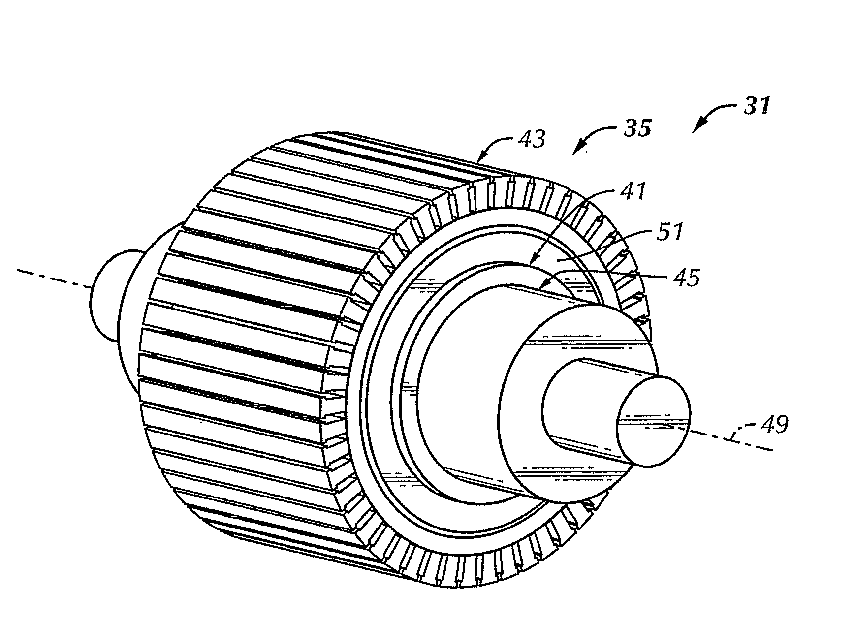
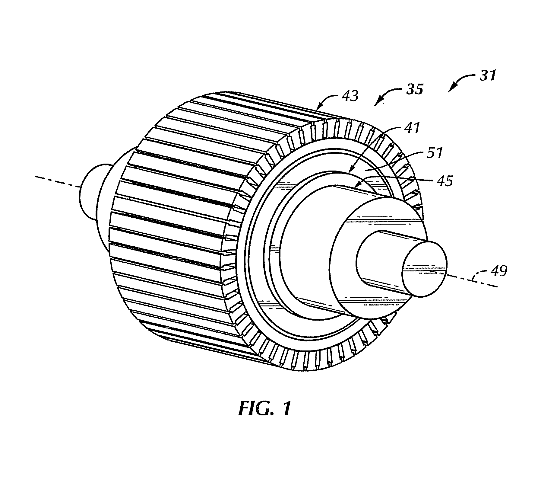
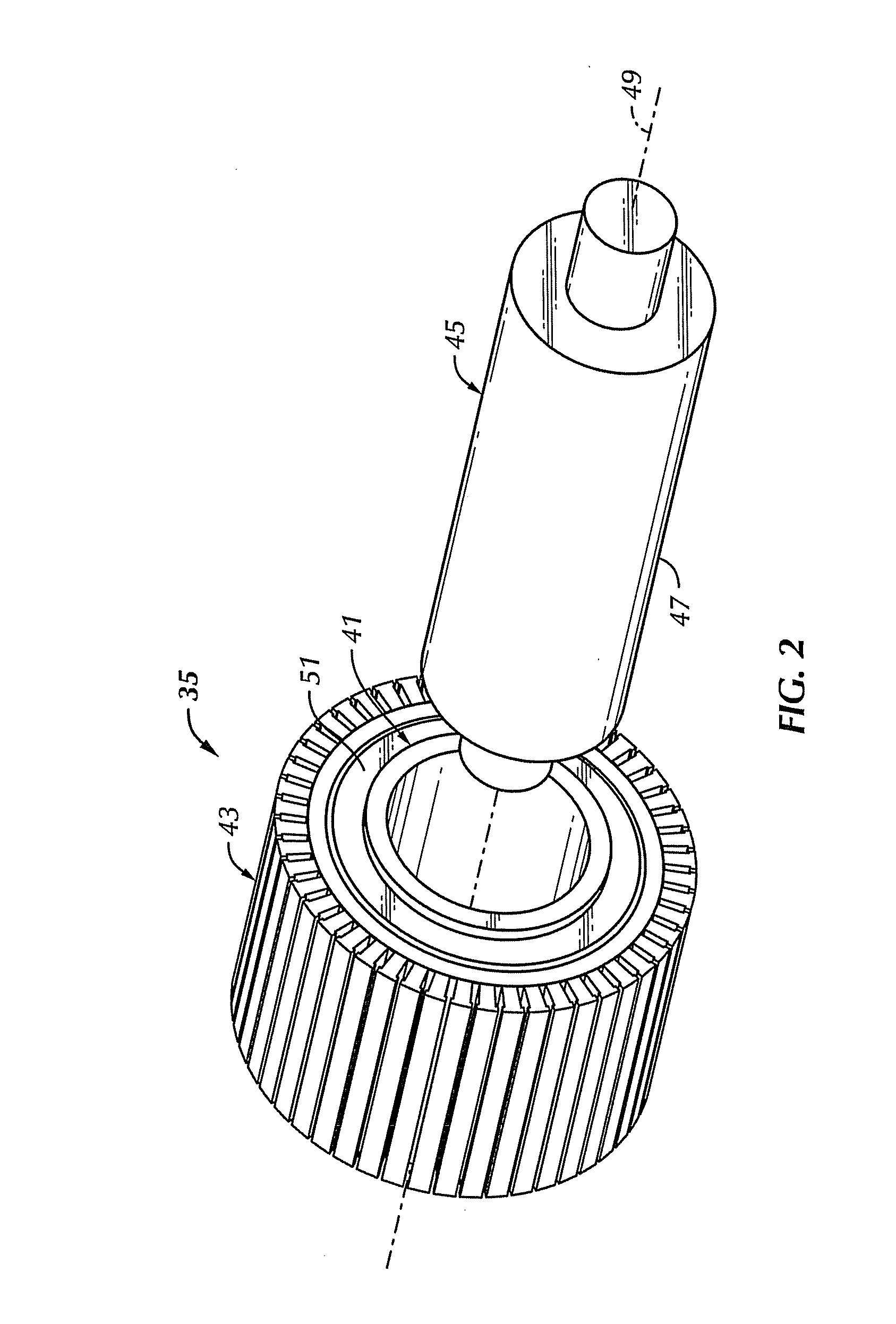
[0039]FIGS. 1-16 illustrate a rotor assembly 31 for a high-speed electric machine and methods of clamping a plurality of laminations 33 to form a rotor core 35 of a high-speed electrical machine according to embodiments of the present invention. In general, embodiments of a rotor assembly 31 includes a tube 41 (e.g., cylindrical) extending through a plurality of laminations 33 ...
PUM
| Property | Measurement | Unit |
|---|---|---|
| speeds | aaaaa | aaaaa |
| diameter | aaaaa | aaaaa |
| outer diameter | aaaaa | aaaaa |
Abstract
Description
Claims
Application Information