
Organic light emitting device with increased luminscence

Active Publication Date: 2008-05-29
SAMSUNG DISPLAY CO LTD
View PDF7 Cites 94 Cited by
  • Summary
  • Abstract
  • Description
  • Claims
  • Application Information

AI Technical Summary

Benefits of technology

[0011]The present invention has been made in an effort to provide an organic light emitting dev

Problems solved by technology

Furthermore, an LCD's response speed and viewing angle are not always ideal.
However, there are practical limitations in the development of a luminescent material of high efficiency, and the method for increasing the amount of current applied to the unit pixel electrodes also has a limitation with respect to life span and efficiency of the OLED and a life span of TFTs.

Method used


Image

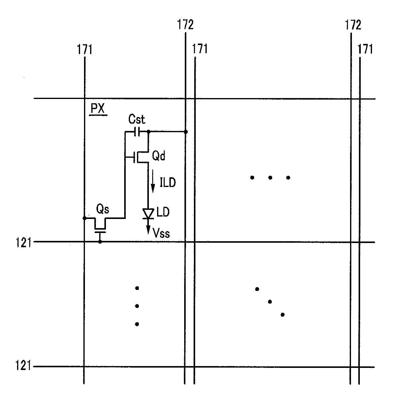
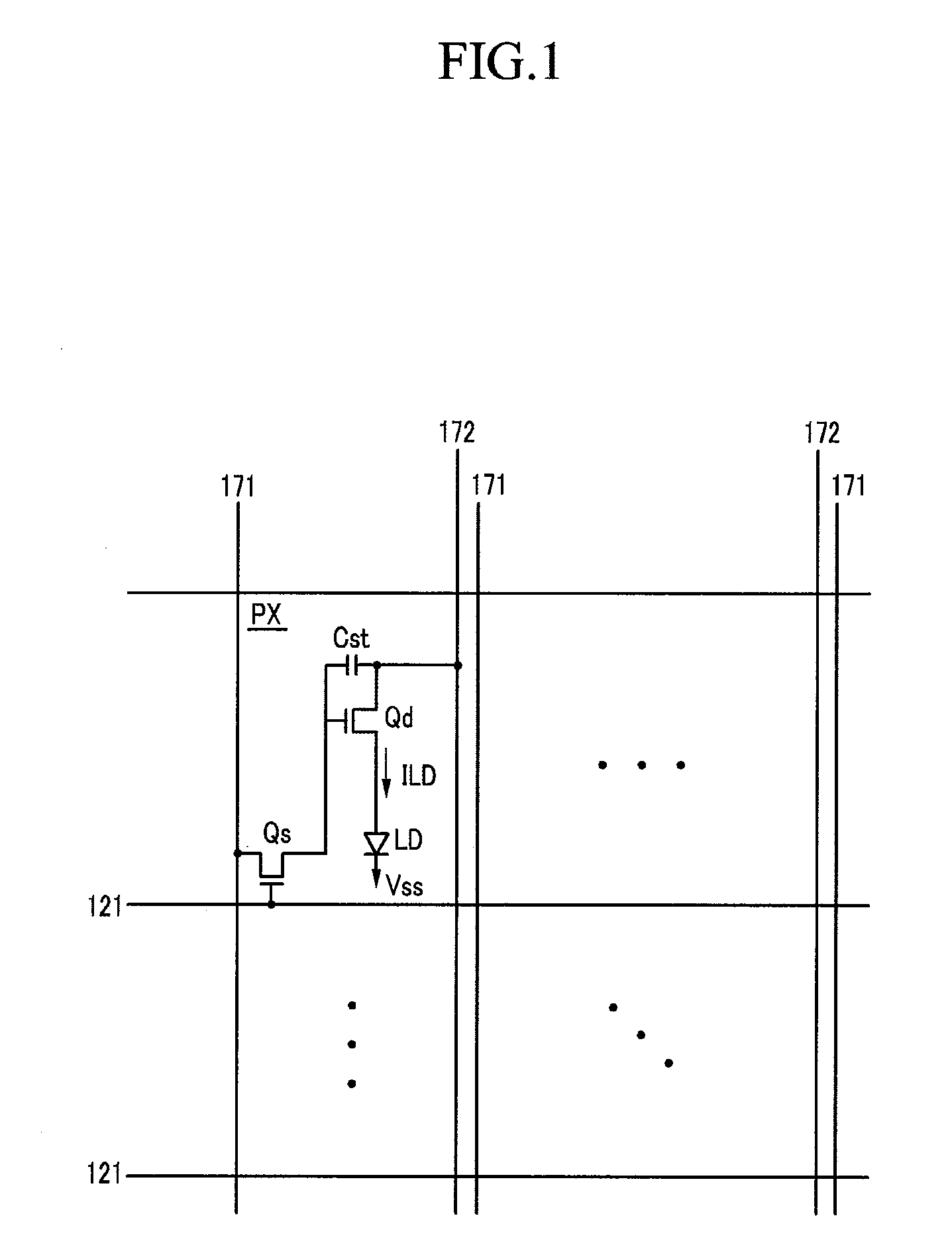
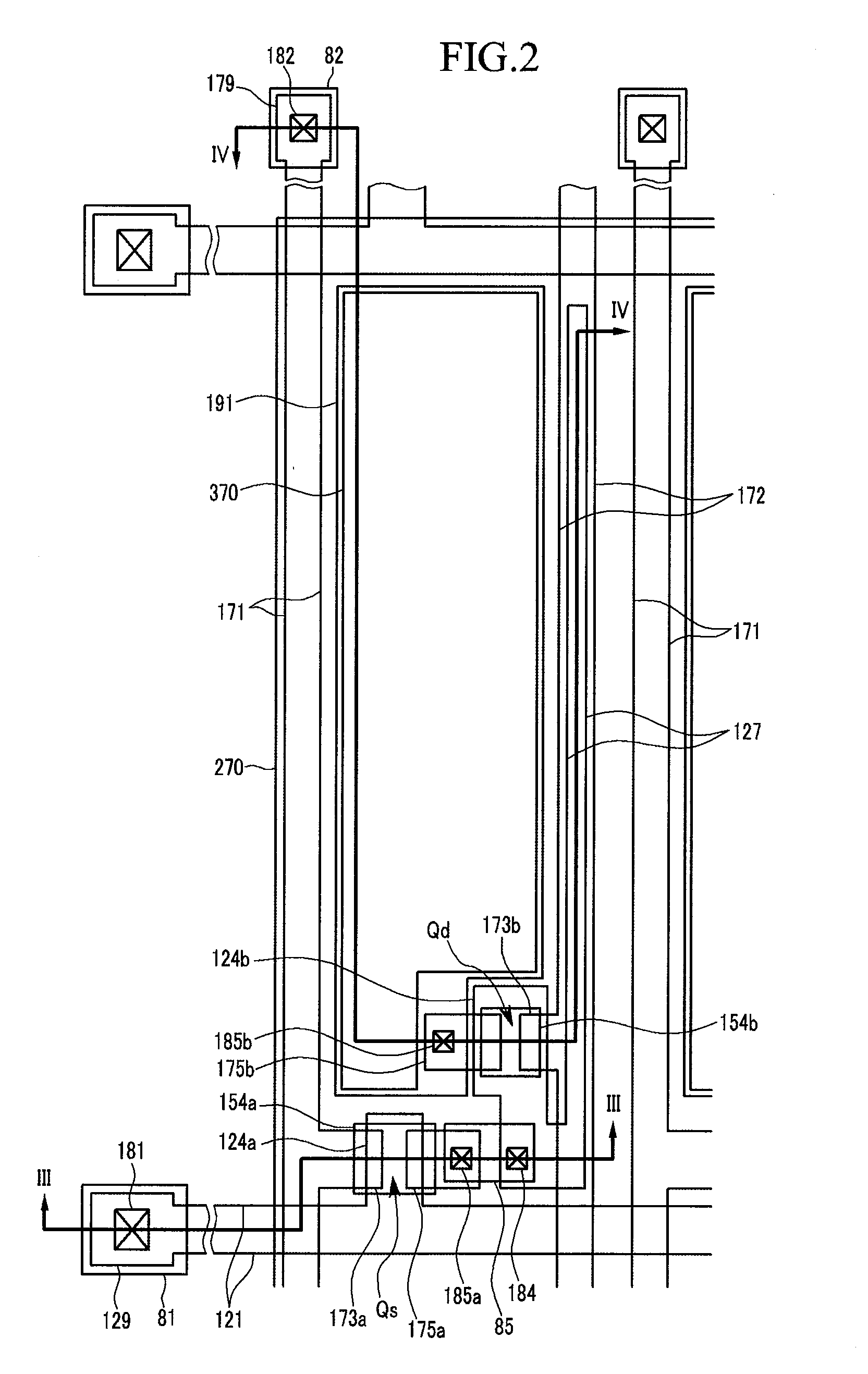
  • Organic light emitting device with increased luminscence
  • Organic light emitting device with increased luminscence
  • Organic light emitting device with increased luminscence

Examples


Embodiment Construction

[0050]The present invention will be described more fully hereinafter with reference to the accompanying drawings, in which exemplary embodiments of the invention are shown. As those skilled in the art would realize, the described embodiments may be modified in different ways without departing from the spirit or scope of the present invention.

[0051]In the drawings, the thickness of layers, films, panels, regions, etc., are exaggerated for clarity. Like reference numerals designate like elements throughout the specification. It will be understood that when an element such as a layer, film, region, or substrate is referred to as being “connected to” another element, it can be directly connected to the other element or intervening elements may be present. In contrast, when an element is referred to as being “directly connected to” another element, there are no intervening elements present.

[0052]The organic light emitting device (OLED) according to respective exemplary embodiments of the...


PUM


Abstract

An organic light emitting device (OLED) is presented that includes: signal lines formed on a substrate; thin film transistors formed on the substrate and electrically connected to the signal lines; a first passivation layer having a concavo-convex surface; a first electrode formed on the first passivation layer; a partition formed on the first electrode and having an opening extending to the first electrode; a light emitting member formed in the opening and covered by a second electrode. The refractive indices of the light emitting member and the first passivation layer are different, and the refractive indices of the first passivation layer and the first electrode are different. The concavo-convex surface increases the luminescent surface area without decreasing the opening size, thereby enhancing the luminous power per unit pixel electrode. Forming an interface of materials whose refractive indices differ by at last 0.2 within the OLED increases light extraction efficiency.

Description

CROSS-REFERENCE TO RELATED APPLICATION[0001]This application claims priority to and benefit of Korean Patent Application No. 10-2006-0117558 filed in the Korean Intellectual Property Office on Nov. 27, 2006, the entire content of which is incorporated herein by reference.BACKGROUND OF THE INVENTION[0002](a) Field of the Invention[0003]The present invention relates to an organic light emitting device (OLED) and its manufacturing method.[0004](b) Description of the Related Art[0005]Recently, as demand for light and thin monitors or televisions has been increasing, cathode ray tubes (CRTs) are gradually being replaced by liquid crystal displays (LCD).[0006]While LCDs have numerous advantages over CRTs, it is not without shortcomings. For example, because an LCD is a non-emissive element, it requires a light source (usually in the form of a backlight). Furthermore, an LCD's response speed and viewing angle are not always ideal.[0007]In search for a display device that does not share the...

Claims


Application Information

Patent Timeline
IPC IPC(8): H01J1/62H01J9/00
CPCH01L27/3244H01L51/5262H01L51/5206H10K59/124H10K59/12H10K50/813H10K50/822H10K50/85H05B33/26H05B33/22
Inventor LEE, BAEK-WOON
Owner SAMSUNG DISPLAY CO LTD
Learn More