Noise filter

a technology of noise filter and surface mount, applied in the field of noise filter, can solve the problem that noise filter cannot be used as a surface-mount component, and achieve the effect of reducing profile and efficiently manufacturing

Active Publication Date: 2008-05-29
MURATA MFG CO LTD
View PDF7 Cites 7 Cited by
  • Summary
  • Abstract
  • Description
  • Claims
  • Application Information

AI Technical Summary

Benefits of technology

[0011]In order to overcome the problems described above, preferred embodiments of the present invention

Problems solved by technology

Therefore, these noise filters cannot be used as a surface-m

Method used


Image

  • Noise filter
  • Noise filter
  • Noise filter

Examples


first preferred embodiment

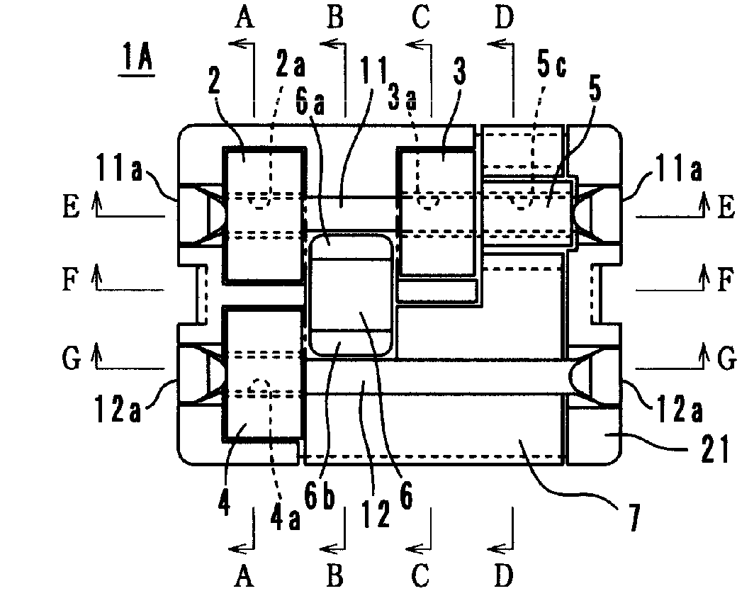
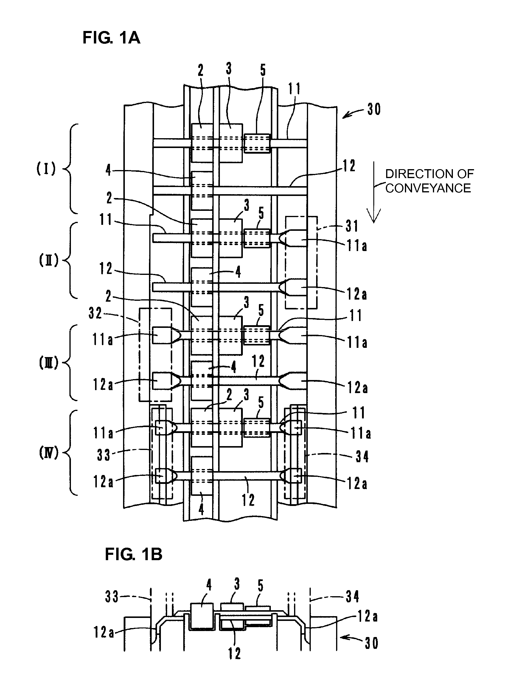
[0036]A noise filter 1A according to a first preferred embodiment is assembled in a manner described below. As illustrated in FIG. 1A(I), a lead 11, which is cut into a predetermined length, is inserted into substantially cylindrical ferrite beads 2 and 3, and a feedthrough capacitor 5. Similarly, a lead 12, which is cut into a predetermined length, is inserted into a substantially cylindrical ferrite bead 4. Each of the leads 11 and 12 is, for example, a lead in which a copper wire of substantially circular cross section having a diameter of about 0.8 mm is dip-soldered. The leads 11 and 12 to which the components 2 to 5 are mounted are placed on a processing conveyer belt 30. The lead 11 is a signal-line lead. The lead 12 is a ground lead.

[0037]The leads 11 and 12 are conveyed by the processing conveyer belt 30, and, as illustrated in FIG. 1A(II), a first end 11a of the lead 11 and a first end 12a of the lead 12 are pressed and flattened by a press jig 31, which is indicated by th...

second preferred embodiment

[0053]As illustrated in FIG. 12, a noise filter 1B according to a second preferred embodiment is one in which the substantially cylindrical ferrite bead 2 and the substantially cylindrical ferrite bead 4 are removed from the noise filter 1A according to the first preferred embodiment. An electrical equivalent circuit in the noise filter 1B is shown in FIG. 13. Other structures are preferably substantially the same as those in the first preferred embodiment. In FIGS. 12 and 13, the same reference numerals are used as in the first preferred embodiment for similar members and portions, and the description thereof is not repeated here.

third preferred embodiment

[0054]As illustrated in FIG. 14, a noise filter 1C according to a third preferred embodiment is one in which the noise filter 1B according to the second preferred embodiment further includes a substantially cylindrical ferrite bead 3A in which the signal-line lead 11 is inserted such that the substantially cylindrical ferrite bead 3A is adjacent to the output of the feedthrough capacitor 5. Other structures are substantially the same as those in the second preferred embodiment. In FIG. 14, the same reference numerals are used as in the second preferred embodiment for similar members and portions, and the description thereof is not repeated here. Compared with the second preferred embodiment, the third preferred embodiment has improved noise reduction characteristics at high frequency by the addition of the substantially cylindrical ferrite bead 3A.

[0055]The noise filter according to the present invention is not limited to the preferred embodiments described above. Various modificati...


PUM


Abstract

In a noise filter, an input side of a signal-line lead is inserted in a first substantially cylindrical ferrite bead, and an output side of the signal-line lead is inserted in a second substantially cylindrical ferrite bead. An input side of a ground lead is inserted in a third substantially cylindrical ferrite bead. The signal-line lead is inserted in a feedthrough capacitor such that the feedthrough capacitor is adjacent to an output side of the second substantially cylindrical ferrite bead. A multilayer capacitor is electrically coupled between the signal-line lead and the ground lead such that the multilayer capacitor is adjacent to an output side of the first substantially cylindrical ferrite bead and adjacent to an output side of the third substantially cylindrical ferrite bead. Each of an end of the signal-line lead and an end of the ground lead is flat, bent along an outer surface of a base member, and defines a surface-mount external terminal.

Description

BACKGROUND OF THE INVENTION[0001]1. Field of the Invention[0002]The present invention relates to noise filters and, in particular, to a noise filter that includes a capacitor.[0003]2. Description of the Related Art[0004]In various types of controlling devices and electronic devices, in order to reduce noise coming through power lines, the incoming noise is filtered out by use of, for example, a noise filter inserted between the power lines.[0005]Such noise filters are described in Patent Documents 1 to 4 (Patent Document 1: Japanese Examined Utility Model Registration Application Publication No. 1-22258; Patent Document 2: Japanese Unexamined Utility Model Registration Application Publication No. 59-22514; Patent Document 3: Japanese Examined Utility Model Registration Application Publication No. 2-18587; Patent Document 4: Japanese Examined Utility Model Registration Application Publication No. 6-31777). For example, a noise filter described in Patent Document 1 includes a multilay...

Claims


Application Information

Patent Timeline
IPC IPC(8): H03H7/00
CPCH01G4/35H03H1/0007H01G4/40H03H7/075H03H7/01
Inventor OSHIMA, HISATOOOI, TAKAAKITANAKA, YOSHIMIMURAKAMI, TOSHINORIYOKOO, KOJI
Owner MURATA MFG CO LTD
Why Eureka
Try Eureka