Electronic Apparatus

a technology of electronic equipment and housing, applied in the direction of lighting and heating equipment, electric equipment casings/cabinets/drawers, instruments, etc., can solve the problems of increased temperature in the housing, degraded space use efficiency in the housing, and long running distance of heat pipes

Active Publication Date: 2008-05-29
TOSHIBA CLIENT SOLUTIONS CO LTD
View PDF11 Cites 32 Cited by
  • Summary
  • Abstract
  • Description
  • Claims
  • Application Information

AI Technical Summary

Benefits of technology

[0007]However, the above electronic apparatus requires a space for providing a pair of heat sinks and a pair of heat pipes, and thereby the space use efficiency in the housing is degraded. Further, in the electronic apparatus, the running distance of the heat pipes is long. Therefore, it is possible that a part of the heat in the heat pipes is released into the housing and causes an increase in temperature in the housing.

Problems solved by technology

However, the above electronic apparatus requires a space for providing a pair of heat sinks and a pair of heat pipes, and thereby the space use efficiency in the housing is degraded.
Further, in the electronic apparatus, the running distance of the heat pipes is long.
Therefore, it is possible that a part of the heat in the heat pipes is released into the housing and causes an increase in temperature in the housing.

Method used


Image

  • Electronic Apparatus
  • Electronic Apparatus
  • Electronic Apparatus

Examples


first embodiment

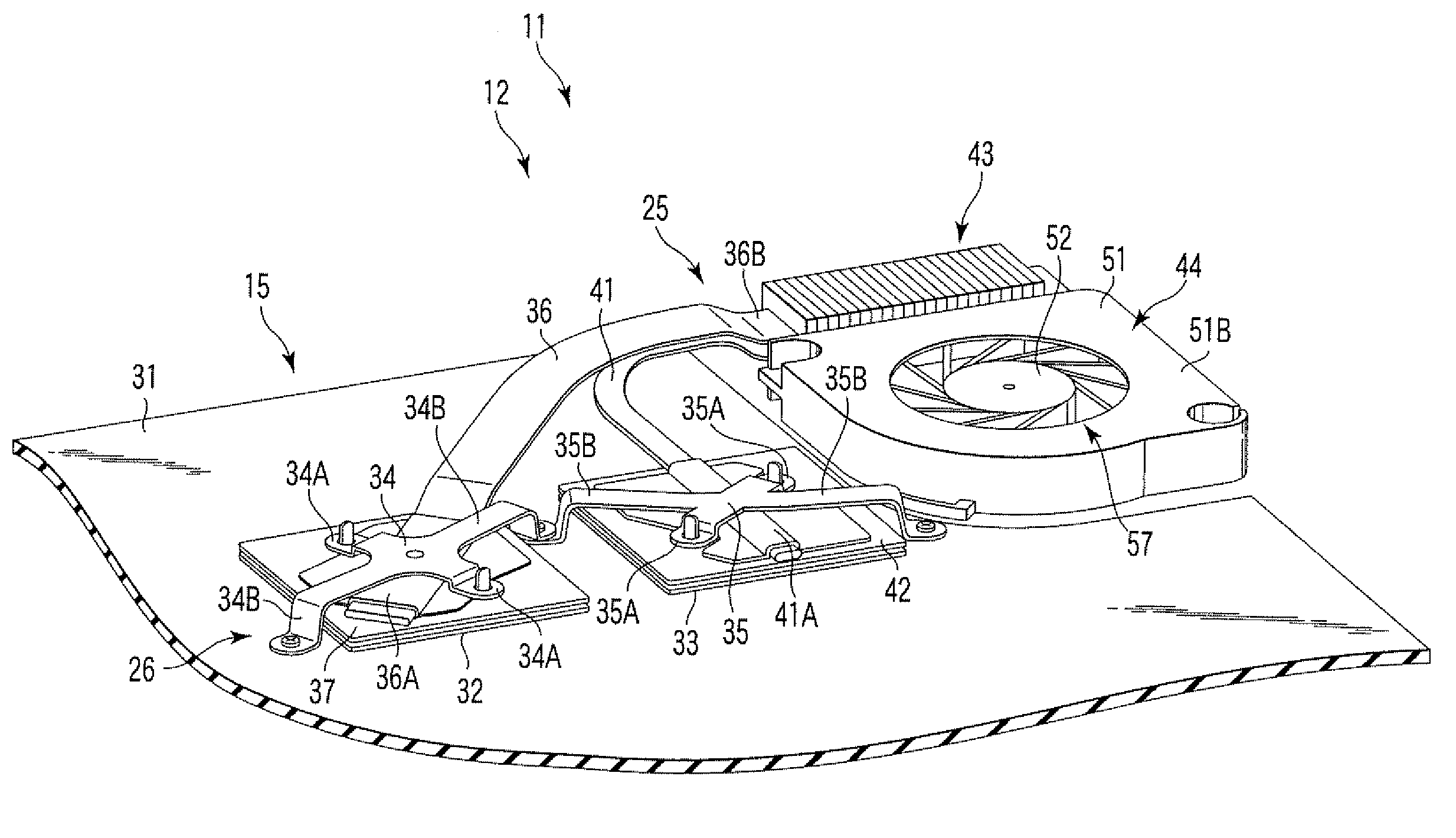
[0024]In the first embodiment, a heat emission amount of the second heat emitter 33 being a north bridge is smaller than a heat emission amount of the first heat emitter 32 being a CPU, Components to be cooled by the cooling device are not limited to the above. Specifically, the first and the second heat emitters 32 and 33 may be other electronic components such as graphics chips, or components such as coils used for a power supply circuit.

[0025]The coupling device 26 has a first coupling metal part 34, and a second coupling metal part 35. The first coupling metal part 34 couples a first heat pipe 36 with the first heat emitter 32. The first coupling metal part 34 has two fixing portions 34A fixed to a first heat receiving part 37, and two arm portions 34B fixed to the printed circuit board 15. A screw hole 34C through which a screw 38 is inserted is provided in a distal end of each of the two arm portions 34B. Further, in the fixing portions 34A, the first coupling metal part 34 is...

second embodiment

[0052] even when the heat sink 73 has a U shape as described above, the mounting space for the cooling device 72 is reduced without degrading the cooling efficiency for the first heat emitter 32 and the second heat emitter 33.

[0053]Next, a third embodiment of the electronic apparatus of the present invention is described with reference to FIGS. 9 and 10. A portable computer 81 being an example of an electronic apparatus according to the third embodiment is basically the same as the first embodiment, except for the structure of a cooling device 82. Therefore, constituent elements of the third embodiment different from the first embodiment are mainly explained, and constituent elements common with the first embodiment are denoted by the same respective reference numerals and explanations thereof are omitted.

[0054]A cooling device 82 of the portable computer 81 has a first heat receiving part 37, a second heat receiving part 42, a first heat pipe 36, a second heat pipe 41, a heat sink ...

third embodiment

[0057] even when the open portion is formed by the through hole 84 as described above, the space used in the housing 21 is reduced without degrading the cooling efficiency for the first heat emitter 32 and the second heat emitter 33.

[0058]The electronic apparatus of the present invention is not limited to portable computers, but the present invention is applicable to other electronic apparatuses such as personal digital assistants (PDAs). Further, the present invention can be variously modified and performed within a range not departing from the gist of the invention.


PUM


Abstract

According to one embodiment, an electronic apparatus has a housing, a first heat emitter and a second heat emitter which are accommodated in the housing, and a cooling device accommodated in the housing. The cooling device includes a heat sink to cool the first heat emitter, a first heat pipe which thermally connects the first heat emitter with the heat sink, a second heat pipe, and a fan unit which cools the heat sink and the second heat pipe. The second heat pipe has a first end portion which is thermally connected to the second heat emitter, and a second end portion which is located near the heat sink.

Description

CROSS-REFERENCE TO RELATED APPLICATIONS[0001]This application is based upon and claims the benefit of priority from Japanese Patent Application No. 2006-317552, filed Nov. 24, 2006, the entire contents of which are incorporated herein by reference.BACKGROUND[0002]1. Field[0003]One embodiment of the invention relates to an electronic apparatus having a cooling device.[0004]2. Description of the Related Art[0005]For example, Jpn. Pat. Appln. KOKAI Pub. No. 2004-213655 discloses the following electronic apparatus having a cooling device. The electronic apparatus has a housing, a semiconductor chip accommodated in the housing, and a cooling device for cooling the semiconductor chip. The cooling device has a pair of connecting blocks to thermally connect with the semiconductor chip, a pair of heat sinks for cooling the connecting blocks, and a fan unit for cooling the connecting blocks. The heat sinks are arranged in positions opposed to a pair of side walls adjacent to a corner portion ...

Claims


Application Information

Patent Timeline
Patent Type & Authority Applications(United States)
IPC IPC(8): H05K7/20F28F7/00
CPCG06F1/203H01L2924/0002H01L2924/00
Inventor TAKEGUCHI, KOICHIROKAWAWA, TATSUYA
Owner TOSHIBA CLIENT SOLUTIONS CO LTD
Why Eureka
Try Eureka