
Built-in steel plate and reactive powder concrete composite shear wall

A technology of combined shear wall and active powder, applied in the direction of wall, building components, earthquake resistance, etc., can solve the problems of reducing the ductility and energy dissipation capacity of combined shear wall, reducing the seismic performance of concrete structures, affecting normal use and durability, etc. , to achieve the effect of easy control of processing quality, improved ductility and energy consumption, and improved ductility

Inactive Publication Date: 2015-04-29
CHANGAN UNIV
View PDF10 Cites 4 Cited by
  • Summary
  • Abstract
  • Description
  • Claims
  • Application Information

AI Technical Summary

Problems solved by technology

However, after the compressive strength of concrete is increased, its tensile and shear strength are relatively low, and the ductility is reduced, thus reducing the seismic performance of concrete structures.
[0004] For the existing ordinary concrete composite shear walls with built-in steel plates, due to the high strength requirements of ordinary concrete, its ductility and crack resistance are relatively weak. In the case of large deformation, the concrete slab may crack and peel off. The effect is greatly weakened, which greatly reduces the ductility and energy dissipation capacity of the composite shear wall under the action of a large earthquake, and the exposure of cracks is inevitable, affecting normal use and durability

Method used


Image

  • Built-in steel plate and reactive powder concrete composite shear wall
  • Built-in steel plate and reactive powder concrete composite shear wall
  • Built-in steel plate and reactive powder concrete composite shear wall

Examples


Embodiment Construction

[0023] The present invention will be described in further detail below in conjunction with the accompanying drawings.

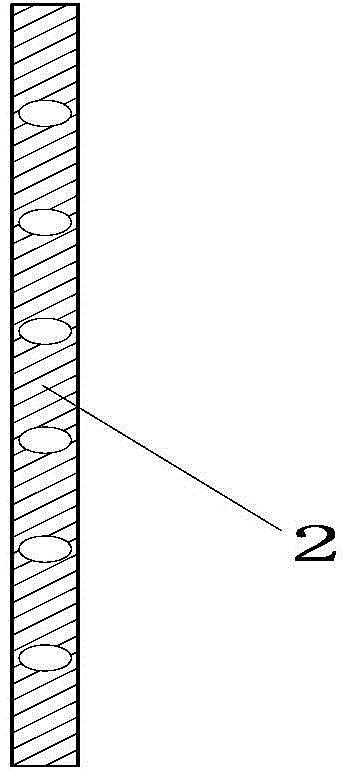
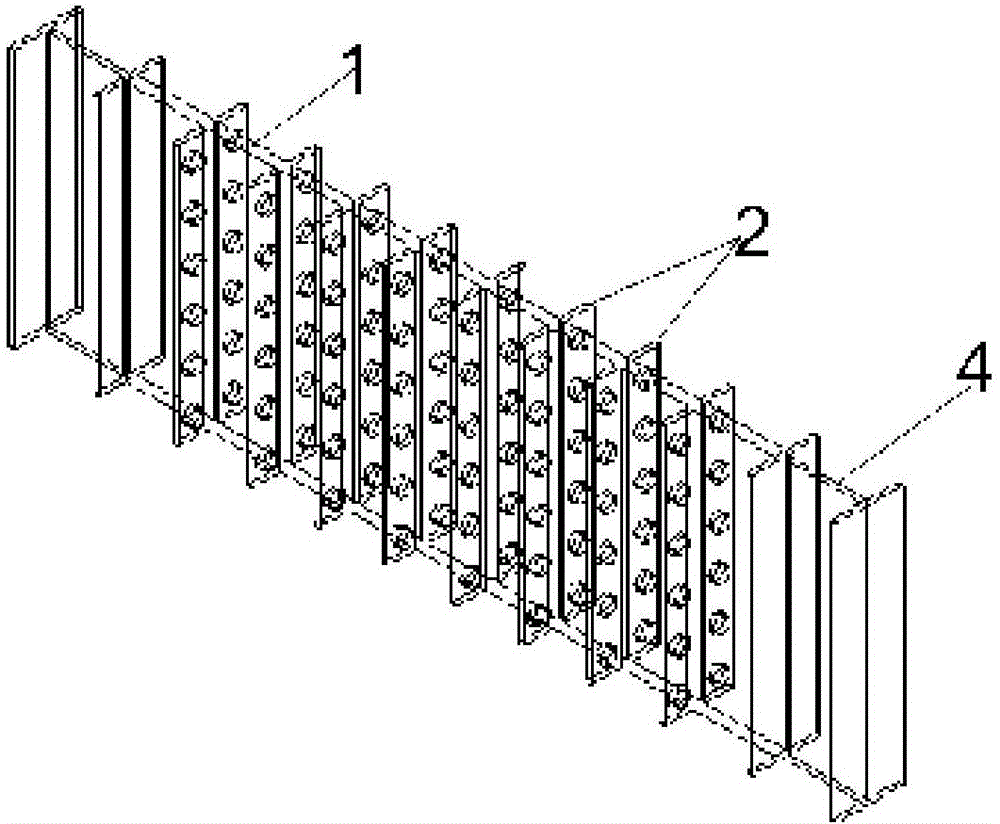
[0024] see Figure 1 to Figure 3 , the active powder concrete composite shear wall with built-in steel plate provided by the present invention comprises a built-in steel plate 1, the built-in steel plate 1 is a single-layer steel plate, several rows of stiffeners 2 with holes are arranged on both sides of the built-in steel plate 1, and on the stiffener 2 with holes A number of elliptical through-holes are evenly opened, the two ends of the built-in steel plate 1 are welded with I-shaped steel, the built-in steel plate 1, the stiffener with holes 2 and the shaped steel 4 are wrapped in the active powder concrete 3, and the built-in steel plate 1 passes through the stiffener with holes 2 Tight connection with reactive powder concrete 3. The stiffeners 2 with holes and the section steel 4 are arranged along the full height of the built-in steel plate 1 . The ...


PUM


Abstract

The invention provides a built-in steel plate and reactive powder concrete composite shear wall which comprises a built-in steel plate. A plurality of rows of stiffening ribs with holes are arranged on two sides of the built-in steel plate, section steel is arranged at two ends of the built-in steel plate, and reactive powder concrete wraps the built-in steel plate, the stiffening ribs with the holes and the section steel. The built-in steel plate and reactive powder concrete composite shear wall has the advantages that respective mechanical properties of the built-in steel plate and the reactive powder concrete can be sufficiently played, the reactive powder concrete not only can be used as a perfect load-bearing and anti-seismic material for a wall body, but also can laterally support the built-in steel plate, and accordingly constraining and protecting effects can be realized for the built-in steel plate; the stiffening ribs with the holes are arranged on the built-in steel plate, accordingly, reactive powder concrete and built-in steel plate coupling effects can be improved, and the problem that an existing built-in steel plate is separated from existing reactive powder concrete in two directions can be solved; the composite shear wall is high in bearing capacity, ductility and energy dissipation capacity under the effects of severe seism and is high in seismic capacity and applicable to high-rise and super high-rise buildings.

Description

technical field [0001] The invention belongs to the field of anti-seismic technology of steel and concrete composite structure and hybrid structure, and in particular relates to a composite shear wall of active powder concrete with built-in steel plates. Background technique [0002] Shear walls are the most important lateral force-resisting structural components of high-rise and super-high-rise buildings. It is very important to develop shear wall systems with good seismic performance. The steel-concrete composite shear wall makes full use of the respective advantages of steel and concrete materials, develops strengths and circumvents weaknesses. It is a low-cost, high-efficiency structural combination form, and it is also a new type of structural system with broad development prospects in my country. [0003] The use of high-strength materials in engineering structures can not only meet the needs of modern engineering structures for high-rise and large-span development, re...

Claims


Application Information

Patent Timeline
Patent Type & Authority Applications(China)
IPC IPC(8): E04B2/58E04B1/98
Inventor 马恺泽阙昂刘超刘伯权
Owner CHANGAN UNIV
Learn More