Optical receptacle

a technology of optical receptacles and receptacles, applied in the field of optical receptacles, can solve the problems of large impact, large impact, and coupling loss, and achieve the effects of avoiding large impact, reducing characteristic variation, and simple structur

Inactive Publication Date: 2008-05-29
FUJITSU LTD
View PDF1 Cites 16 Cited by
  • Summary
  • Abstract
  • Description
  • Claims
  • Application Information

AI Technical Summary

Benefits of technology

[0032]The present invention has been developed in consideration of the above-mentioned problems, and it is therefore an object of the invention to provide an optical receptacle with a simple structure, which avoids the occurrence of a large impact by preventing a plug body from coming into collision with an optical propagation member such as a fiber stub or a glass plate due to a force of an elastic body of a terminal member at the insertion of the terminal member while reducing a characteristic variation at the application of a load to a cord.
[0040]Thus, as an advantage, the present invention can provide an optical receptacle with a simple structure, which avoids the occurrence of a large impact due to the collision of a plug body with an optical propagation member by a force of an elastic body of an optical connector plug at the insertion of the optical connector plug while reducing a characteristic variation at the application of a load to a cord.

Problems solved by technology

In such a situation, a coupling loss occurs, and in the case of the TOSA, the optical output fluctuates.
However, the inventor of the subject application found that the precision sleeve 142 has the following problems.
At this time, there is a problem in that a large impact exceeding, for example, 10,000 G occurs since the ferrules 106 and 122 made of a hard material such as zirconia come into collision with each other.
Such a large impact leads to that the fiber stub 108 inserted under pressure settles down or the performance of precise electronic parts mounted in the interior of the package 104 suffers degradation.
No employment of the spring 123 makes it difficult to bring the plug ferrule 122 into contact with the fiber stub 108 or the glass plate 116, which leads to the occurrences of reflection and coupling loss.

Method used


Image

  • Optical receptacle
  • Optical receptacle
  • Optical receptacle

Examples


first embodiment

[a] Description of First Embodiment of the Present Invention

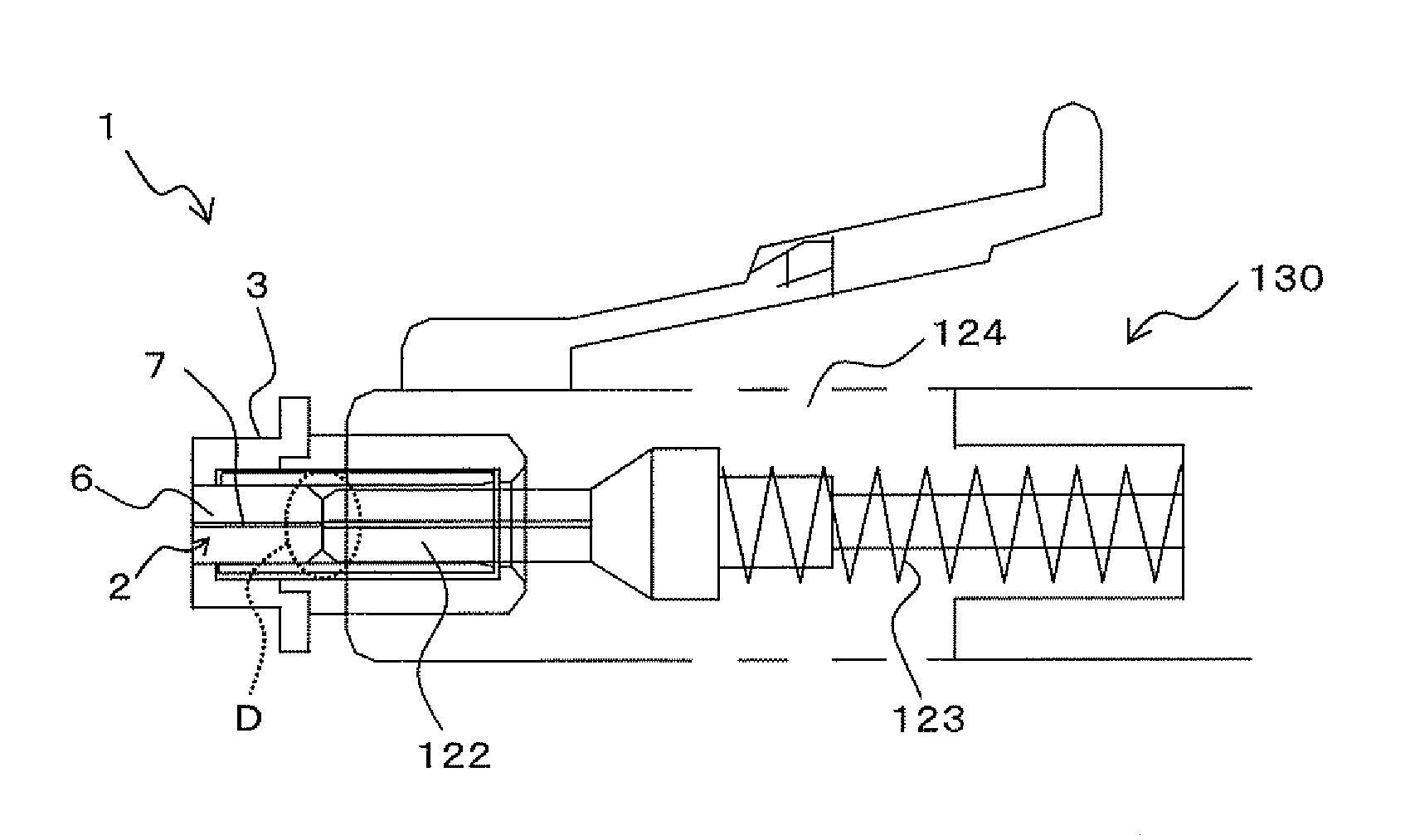
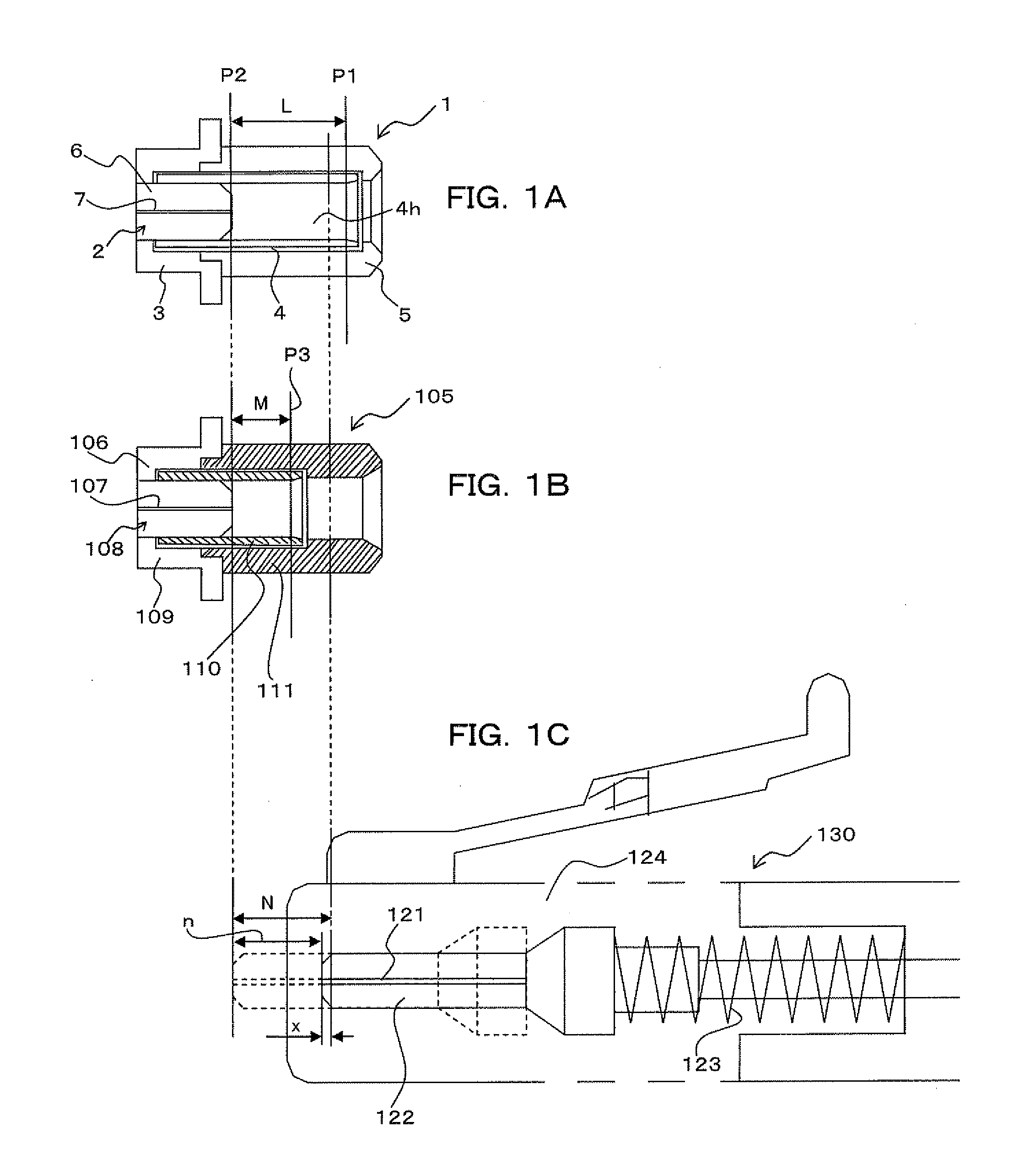
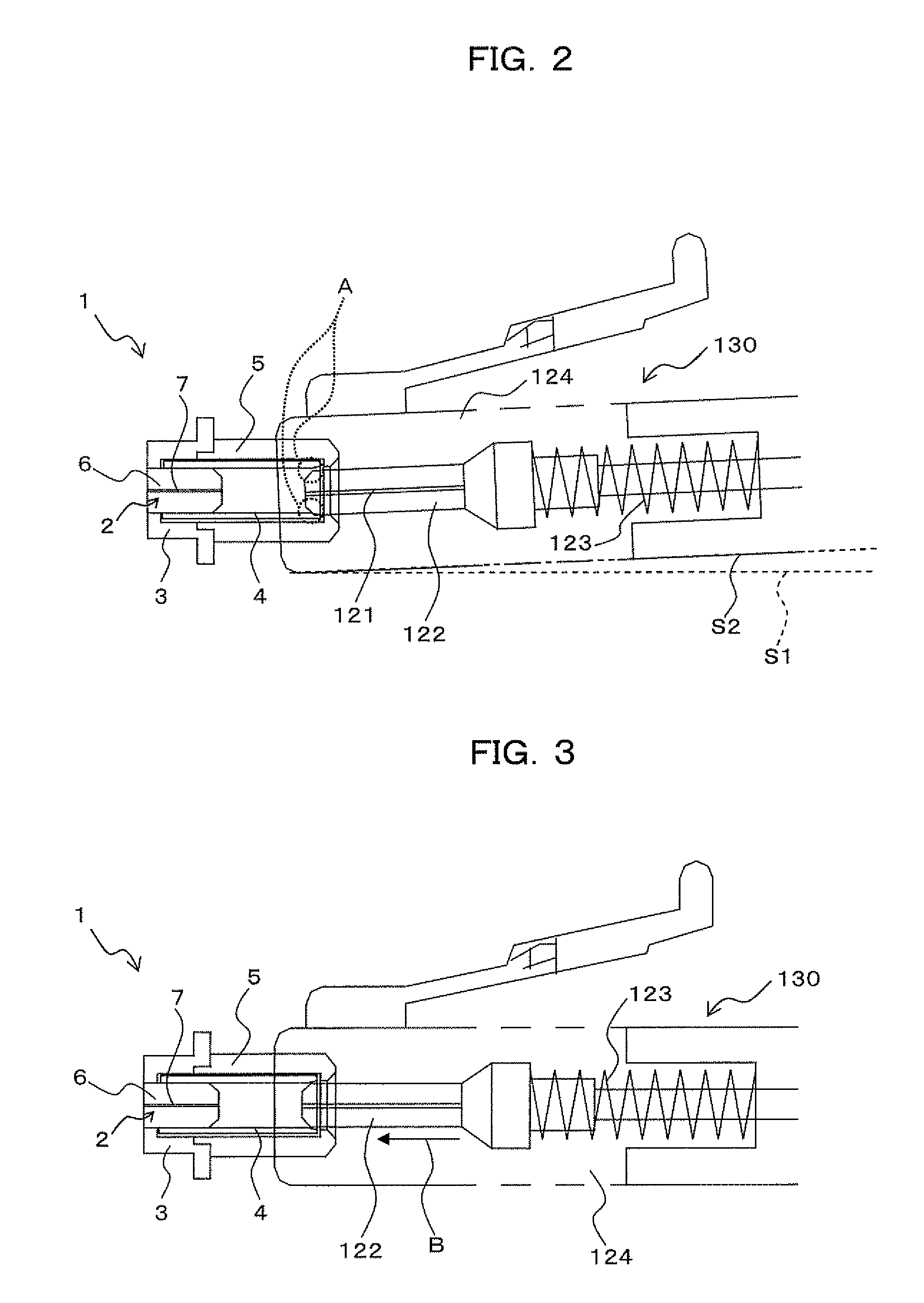
[0058]FIG. 1A is a cross-sectional view showing an optical receptacle 1 according to a first embodiment of the present invention, and FIG. 1C is a cross-sectional view showing an optical connector plug 130 to be inserted into the optical receptacle 1. The optical receptacle 1 according to the first embodiment is applicable as an optical receptacle for an LC connector for use in a TOSA and ROSA to be mounted in a pluggable type optical transceiver module such as an SFP or XFP. That is, the optical receptacle 1 can accept an terminal member such as the optical connector plug 130 shown in FIG. 1C (FIG. 9) for optical coupling.

[0059]As mentioned above, the optical connector plug 130 includes a plug ferrule 122 which is a plug body through which a first optical fiber 121 passes, a spring 123 which serves as an elastic body whereby the plug ferrule 122 is extensible and contractible in a direction of the passing of the first opti...


PUM


Abstract

The present invention relates to an optical receptacle which prevents the occurrence of a large impact by collision of a plug body with an optical propagation member. The optical receptacle includes a solid sleeve having a cavity hole into which the plug body is inserted from its one end side and which has an even inner diameter so as not to substantially define a gap with respect to an outer diameter of the plug body and an optical propagation member fixedly secured to the other end side of the cavity hole, with the solid sleeve being formed such that a length from an end portion of the cavity hole on the plug body insertion side to the optical propagation member is longer than a maximum length of extension due to the elastic body of the terminal member.

Description

BACKGROUND OF THE INVENTION[0001]1) Field of the Invention[0002]The present invention relates to an optical receptacle suitable for use in TOSA (Transmitter Optical Sub Assembly) or ROSA (Receiver Optical Sub Assembly) to be mounted in a pluggable type optical transceiver module such as SFP (Small Form-Factor Pluggable) or XFP (10 Gigabit Small Form-Factor Pluggable).[0003]2) Description of the Related Art[0004]In recent years, along with the establishment of the MSA (Multi Source Agreement) for a pluggable type optical transceiver module such as SFP or XFP, it has come into widespread use in optical communication systems based upon SONET / SDH (Synchronous Optical NETwork / Synchronous Digital Hierarchy) and Ethernet (registered trademark). In this pluggable type optical transceiver module, optical assemblies with transmission and reception functions, such as TOSA (Transmitter Optical Sub Assembly) and ROSA (Receiver Optical Sub Assembly), are mounted in packages specified in dimension...

Claims


Application Information

Patent Timeline
Patent Type & Authority Applications(United States)
IPC IPC(8): G02B6/38
CPCG02B6/3874G02B6/4246G02B6/3893
Inventor MITAMURA, NOBUAKI
Owner FUJITSU LTD
Why Eureka
Try Eureka