Urinary catheter with check valve

a technology of check valve and urinary catheter, which is applied in the direction of catheters, suction devices, medical science, etc., can solve the problems of catheter not being able to be used for irrigation, passageway becoming very susceptible to blockage, and deathly infections, so as to prevent the backflow of drained fluid

Inactive Publication Date: 2008-05-29
MARISI MARGARET GRAHN
View PDF51 Cites 9 Cited by
  • Summary
  • Abstract
  • Description
  • Claims
  • Application Information

AI Technical Summary

Benefits of technology

[0011]The second advantage provided by placing the valve in this particular position is that it is located physically outside the patient body when the catheter is placed in the operable position. In this manner, the catheter construction insures that not only will the backflow of drained fluid be prevented, but backflow along the entire length of the entire catheter is also prevented in contrast to the devices of the prior art. Another advantage of the present invention is that when employed in a single lumen or double lumen catheter construction, the valve is located at a point well outside the body of the patient. In this manner, a second entry port into the drainage lumen at a point upstream from the valve may be provided if desired to allow irrigation through the catheter as has been previously unknown in the art. With the prior art devices of this type, the only way to facilitate irrigation is through the use of a triple lumen catheter. This is because in the prior art the valve was located at the insertion end of the catheter, well within the body of the patient, where it would be impossible to introduce an additional entry port upstream from the check valve.
[0012]Finally, since the valve of the present invention is located in a section of the lumen where the cross sectional area is larger, it is less likely to become clogged by for example, crystals that may be suspended in the patient's urine.
[0013]Accordingly, one of the objects of the present invention is the provision of a novel catheter construction that provides protection against the backflow of drained fluid. Another object of the present invention is the provision of a novel catheter construction that prevents that backflow of drained fluid from reentering the body of the patient being treated. A further object of the present invention is the provision of a catheter construction that can be employed equally with the various types of existing catheter configurations to prevent the backflow of drained fluid while further allowing the use of the central lumen for irrigation if necessary. Yet a further object of the present invention is the provision of a catheter construction that prevents the backflow of drained fluid while including a positive interlocking mechanism for the attachment of accessories such as drainage collection containers.

Problems solved by technology

The difficulty is that as described above, the catheter tube is connected at the outflow end to a collection container.
In these cases, the drained fluid may remain in the drainage container for several hours allowing the growth of harmful bacteria.
Should this fluid be reintroduced to the body cavity serious or even deadly infections could result.
First, because of the size and location of the valve, in the narrowest diameter of the catheter, the passageway becomes very susceptible to blockage.
Finally, if this valve configuration is used in a double or single lumen design, the catheter cannot be used of irrigation because the valve would block the flow of injected irrigation fluid.

Method used


Image

  • Urinary catheter with check valve
  • Urinary catheter with check valve
  • Urinary catheter with check valve

Examples


Embodiment Construction

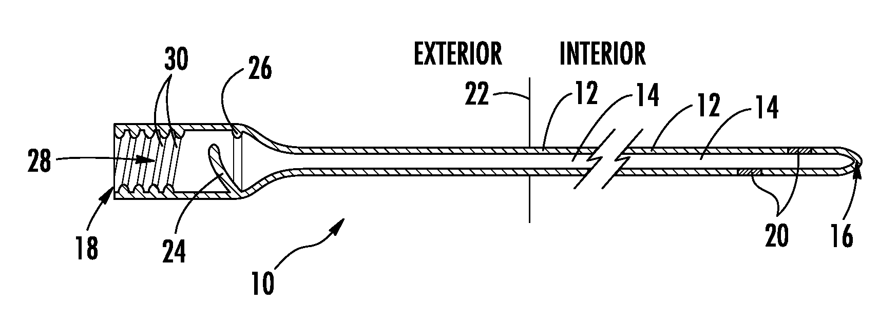
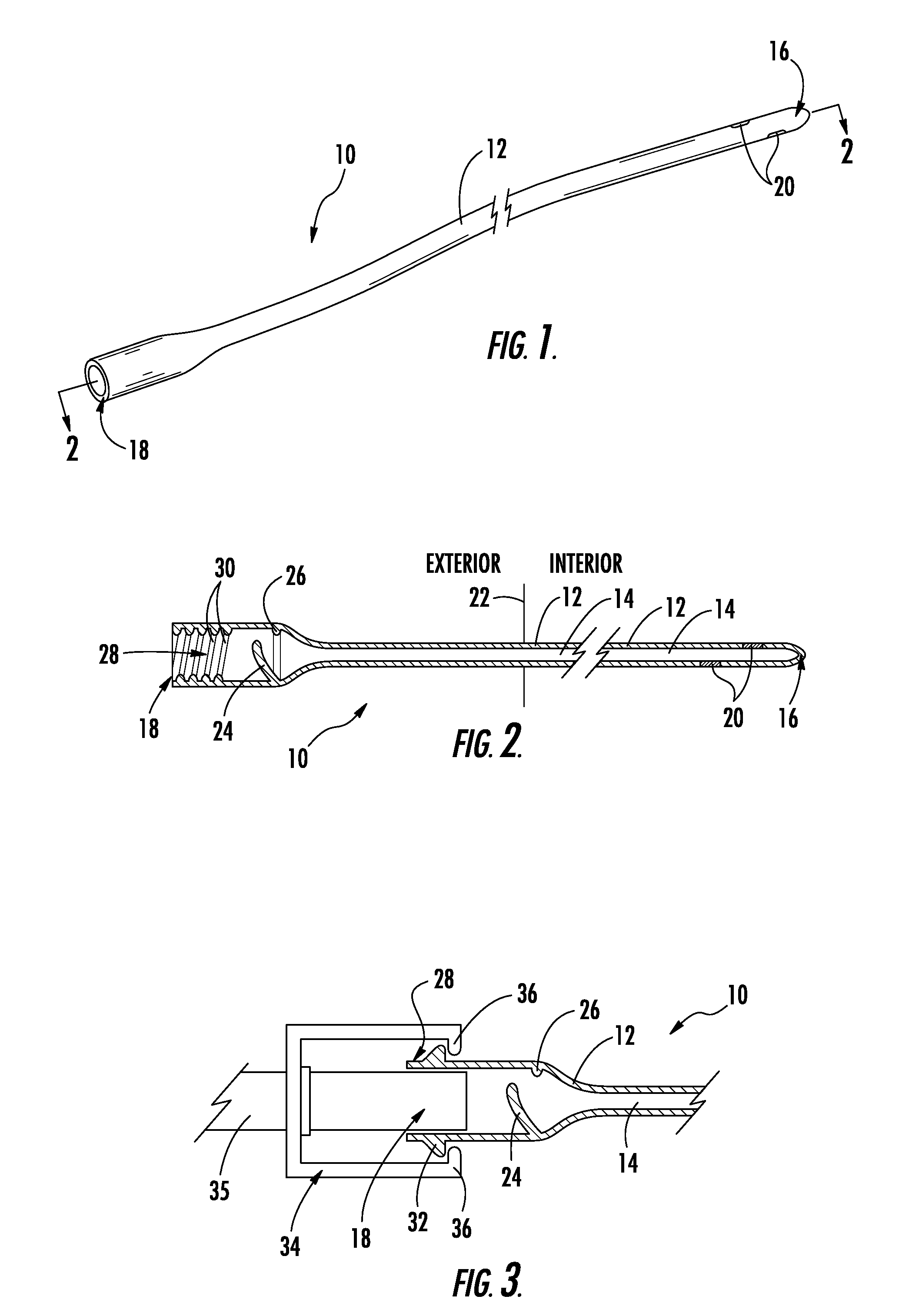
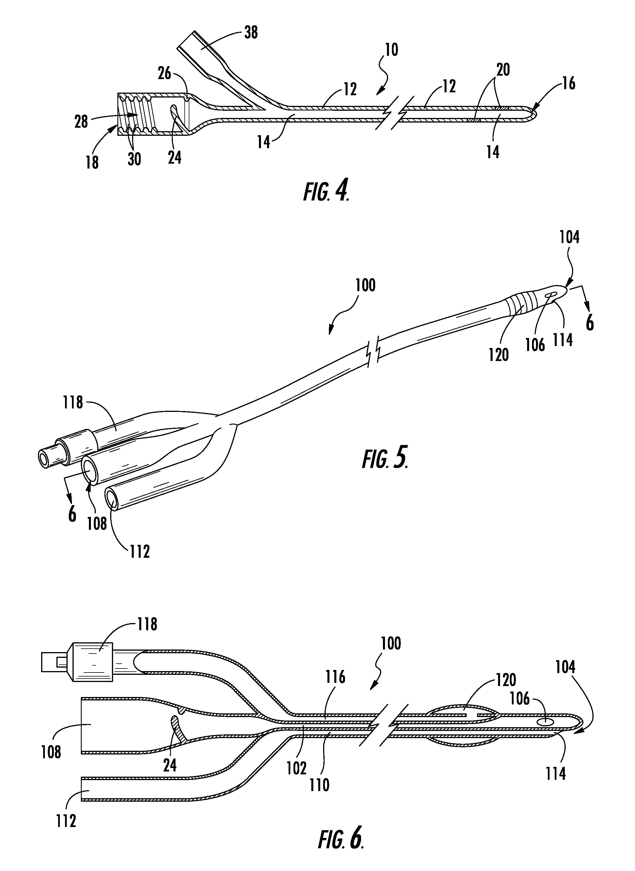
[0022]Referring now to the drawings, the novel catheter construction of the present invention is illustrated and generally indicated as 10 in FIGS. 1-6. Turning now to FIG. 1, the general shape of the catheter 10 of the present invention has a long tubular body 12 that includes at least one hollow passageway 14 therein and is provided with an inlet end 16 and an outlet end 18. Typically, the entire catheter 10 will be formed from a single elastomeric material such as silicone or a natural latex rubber. The inlet end 16 is formed as a narrow portion of the elongated tube 12 with a rounded or slightly tapered end to facilitate insertion into a body cavity. For example, in the case of the present invention the end is rounded to allow insertion through the external urethral opening and into the bladder. At least one opening 20 is provided at the inlet end 16 of the catheter 10 to allow fluid from the body cavity to enter the hollow passageway 14 on the interior of the catheter 10. The h...


PUM


Abstract

The present invention provides a novel construction for a catheter that includes backflow prevention in the form of a check valve, which keeps the flow of drained fluid material from reentering the patient. The catheter construction of the present invention provides a standard single or multiple lumen tube assembly that extends rearwardly from the insertion end of the catheter to the contact end wherein on the discharge lumen a one way check valve is provided. It is an important feature of the present invention that the check valve is provided as close to the terminal end of the contact end as possible without interfering with the necessary accessory attachment that is typically made thereto. Further, an interlock mechanism may be provided at the terminal end of the catheter for connecting accessories in a positive locking manner. The combination of the valve and the interlock mechanism provides a notable safety and performance improvement that has been previously unknown in the prior art.

Description

CROSS-REFERENCE TO RELATED APPLICATIONS[0001]This application is related to and claims priority from earlier filed U.S. Utility patent application Ser. No. 10 / 248,888, filed Feb. 27, 2004, now U.S. Pat. No. 7,331,949, issued Feb. 19, 2008.BACKGROUND OF THE INVENTION[0002]The instant invention relates generally to novel construction for a urinary catheter device. More specifically, the present invention relates to a urinary catheter device that includes a backflow prevention valve that is located in the catheter tube at a point outside the patient's body, providing improved construction and a safer location relative to the prior art devices.[0003]Catheters and other devices for use in the draining of accumulated fluids from the human body or injecting fluids into the body have been widely used in the medical field for a long period of time. In particular, with reference to catheters, there are numerous constructions and designs, each of which is particularly adapted to be inserted in...

Claims


Application Information

Patent Timeline
Patent Type & Authority Applications(United States)
IPC IPC(8): A61M27/00A61F5/44
CPCA61F5/4405A61M25/0097
Inventor MARISI, MARGARET GRAHN
Owner MARISI MARGARET GRAHN
Why Eureka
Try Eureka