Traffic safety pylon with GPS locating and RF signalling

a technology of traffic safety and pylons, applied in the field of intelligent traffic cones or pylons, can solve the problems of no traffic safety cones, time lags, real time traffic flow,

Inactive Publication Date: 2008-05-29
CALMAR HLDG
View PDF5 Cites 32 Cited by
  • Summary
  • Abstract
  • Description
  • Claims
  • Application Information

AI Technical Summary

Benefits of technology

[0004]Accordingly, it is an object of the present invention to provide a process for providing motor vehicle operators with real-time status of roadway conditions, including the locations of obstructions, blockages and outages, in a way that avoids the drawbacks of the prior art.
[0006]Another object is to provide such a pylon that can be easily set out by a road crew at one or both ends of a section of roadway or a traffic lane, and can be easily picked up at the end of construction for use elsewhere or for storage.
[0008]The pylon has a GPS sensor at its top, a microprocessor circuit within the body of the pylon, and a radio transmitter in the pylon body. The microprocessor circuit is coupled to the GPS sensor to acquire location data for the pylon. These data are obtained with a resolution of about five feet (one and one-half meters) or less, i.e., within about one half the width of a traffic lane. The microprocessor is coupled to the transmitter, and the latter provides a radio signal that is modulated with the traffic location data. This signal is fed to an antenna mounted on the pylon body and the signal is sent to a receiver for a central traffic navigation facility. Other information can be detected and sent on the radio signal as well, e.g., traffic density, average traffic speed, temperature, rainfall, or other weather data. The central facility obtains accurate locations for each of the pylons that are set out, and is able to identify the commencement and termination of each traffic obstruction, which may be a traffic accident site, or a segment of a roadway lane under construction or repair, for example. The central facility then processes these data, and provides accurate navigation data wirelessly to motor freight operators and / or other motor vehicle operators which are equipped with an in-cab navigation system. The data can also be sent via wireless or landline means to the carrier's dispatch office and / or to police departments and traffic patrols.
[0009]The pylons are easily set out by road construction or repair crews, or by highway patrol or other public safety officers, and can be easily turned on. Once this is done, each traffic cone or pylon obtains its location via its GPS circuitry, and then communicates its identification and its location to the central traffic navigation facility. These pylons update their status on a regular basis, e.g., each several minutes or each hour, so that the central facility is continually apprised of the status of each identified roadway obstruction or hazard.

Problems solved by technology

However, to date there have been no traffic safety cones that incorporate means for automatically identifying the cone and its specific geographical location, and for automatically communicating that information to a central facility.
However, these data typically have to be keyed in manually, which can lead to time lags between commencement of a traffic delay and the appearance of the relevant data on the roadway navigation service.
Also, real time traffic flow information, such as traffic density, average traffic speed, weather conditions, for given points along the roadway, are difficult or impossible to obtain, and these data are difficult to update and maintain.
No one has proposed any effective technique for real-time or near-real-time updates of traffic data of this nature.

Method used


Image

  • Traffic safety pylon with GPS locating and RF signalling
  • Traffic safety pylon with GPS locating and RF signalling
  • Traffic safety pylon with GPS locating and RF signalling

Examples


Embodiment Construction

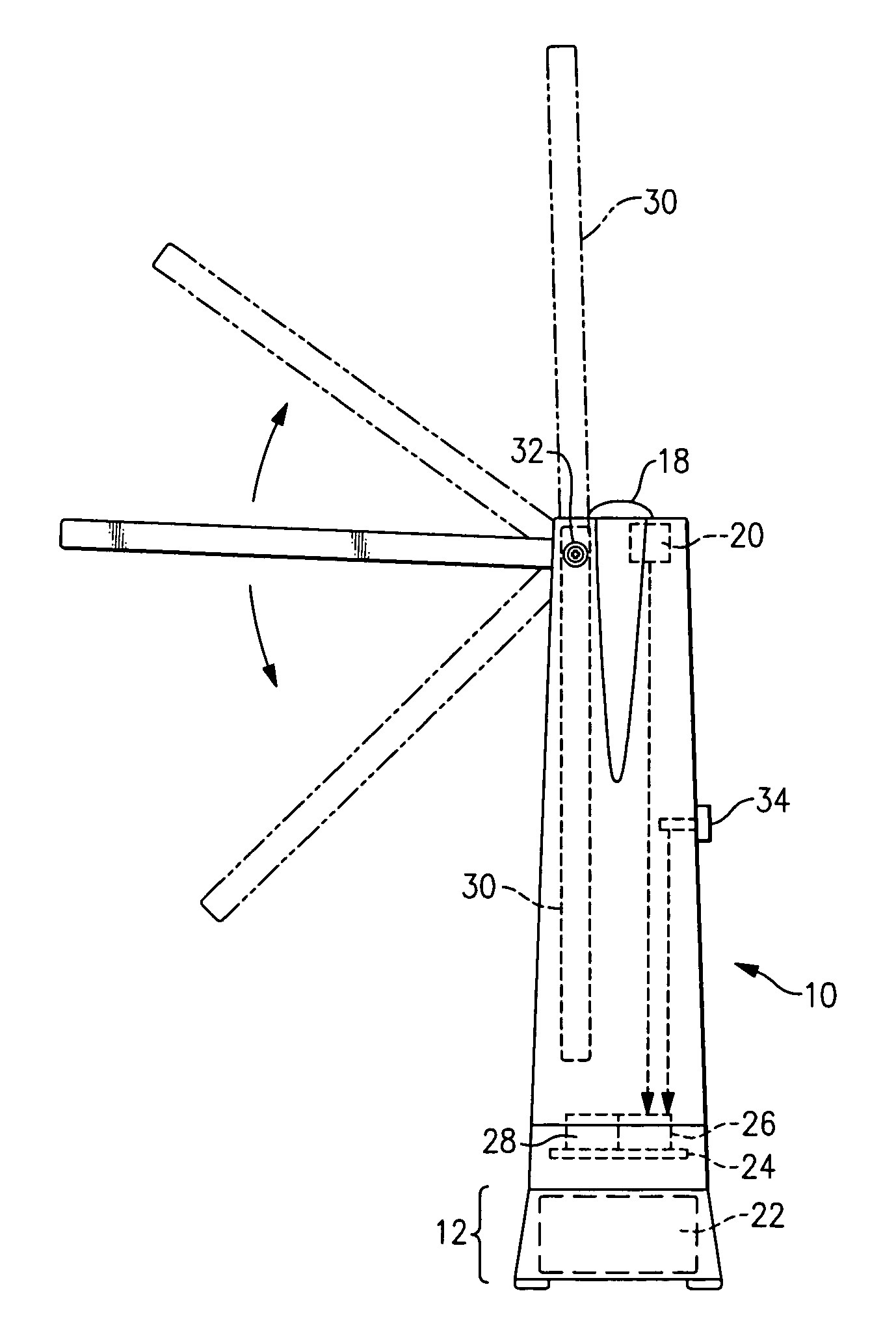
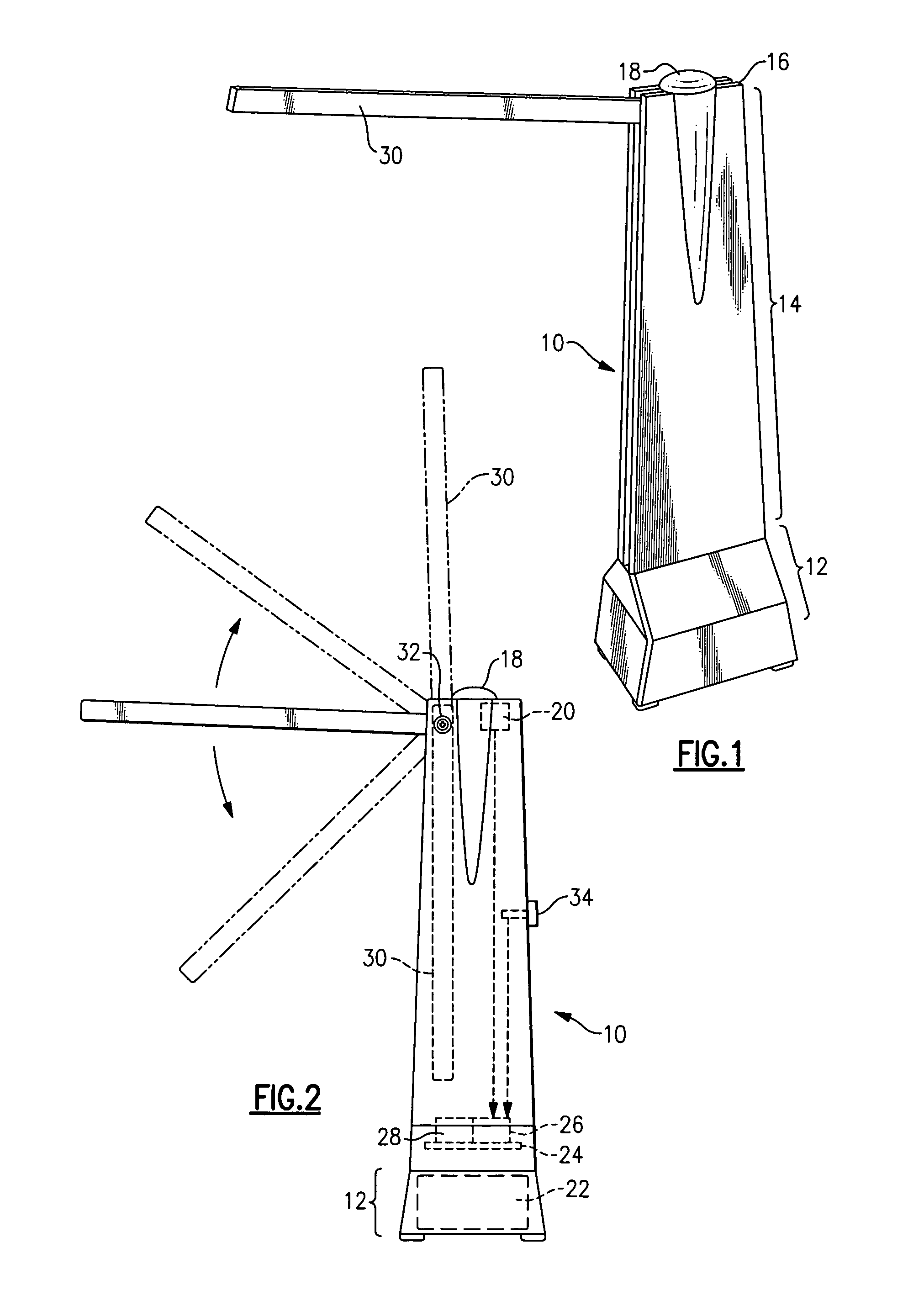
[0015]With reference now to the Drawing, FIG. 1 shows a traffic safety pylon 10 or traffic cone, which has a base 12 at its lower end for resting on a roadway surface, and a body portion 14 that rises upward from the base 12 to a top 16. Within a dome 18 at the top is located a GPS receiver 20 (see FIG. 2). Placed here at the dome 18, the GPS receiver 20 will have the best view of the sky to receive the navigation signals from a constellation of navigation satellites. As the satellites orbit past again and again, the location information for the pylon becomes more and more fine-tuned, i.e., the accuracy of the data becomes better. The resolution of the location data in a short while reaches about one-half the width of a lane of traffic. This allows the pylon 10 to identify fairly precisely the end of the traffic lane where it has been placed, and to identify the specific lane of a multi-lane highway where the traffic obstruction exists.

[0016]A battery 22 is mounted within the base 1...


PUM


Abstract

An intelligent traffic safety cone or pylon is placed in a traffic lane of a roadway to mark the beginning or end of a roadway traffic obstruction. The pylon has a GPS sensor disposed at the top of the body portion that rises from the pylon base. A battery is situated within the pylon base providing stabilizing weight. A microprocessor circuit within the pylon body is coupled to the GPS sensor to acquire location data of said pylon to within a resolution of a lane of the roadway. A radio transmitter within the pylon body coupled to the microprocessor provides a radio signal modulated to provide the location data to a central traffic navigation facility. The pylon may have a folding antenna, and may have additional sensors for traffic conditions and weather conditions.

Description

BACKGROUND OF THE INVENTION[0001]This invention relates to traffic safety, and to remote monitoring of roadway traffic conditions. The invention is more particularly concerned with an intelligent traffic cone or pylon, which can be placed at one end of a roadway obstruction or traffic delay, such as a road construction or repair, and which can communicate its location and other information to a central traffic navigation facility.[0002]Traffic safety cones or pylons and other typical traffic safety barriers can typically be lightweight, highly visible articles used to mark a traffic obstruction. These typically are passive devices which employ reflective tape for increased visibility and in some cases may include a lamp, flashers, or the like. However, to date there have been no traffic safety cones that incorporate means for automatically identifying the cone and its specific geographical location, and for automatically communicating that information to a central facility.[0003]It ...

Claims


Application Information

Patent Timeline
Patent Type & Authority Applications(United States)
IPC IPC(8): G01C21/02
CPCE01F9/005E01F9/0112G08G1/0955G01S19/14E01F9/0122E01F9/30E01F9/61E01F9/65E01F9/654E01F9/688
Inventor SCHECKLER, ROSS D.
Owner CALMAR HLDG
Why Eureka
Try Eureka