Sheet metal forming process

a metal sheet and forming technology, applied in metal-working apparatus, manufacturing tools, shaping tools, etc., can solve the problems of metal failure or fatigue, inability to use or scrap parts, and limited processes, so as to improve the forming aspect ratio, reduce the forming time, and improve the forming efficiency

Inactive Publication Date: 2008-06-05
FORD GLOBAL TECH LLC +2
View PDF21 Cites 16 Cited by
  • Summary
  • Abstract
  • Description
  • Claims
  • Application Information

AI Technical Summary

Benefits of technology

[0011]The method includes developing a preform geometry that reduces forming time and improves panel mobility during the gas or superplastic forming cycle by improving the forming aspect ratio, requiring less part or metal stretch to form over small radii and the ability to draw additional material from the binder area to reduce the amount of thinning required to form the part.

Problems solved by technology

Such processes are typically limited by the material's ability to be strained past its rupture point.
Thus, depending upon the complexity of the part, the forming stresses on the metal sheet during the forming process may result in metal failure or fatigue and correspondingly an unusable or scrap part.
Superplastic forming does have a disadvantage in that it normally requires relatively long forming cycle times. Specifically, a conventional SPF process used to manufacture a complex part can require a forming cycle time as high as 30 minutes.
Further, superplastic forming cannot always be used to obtain a complex part in a single step and therefore may require two or more forming steps.
While this die structure and corresponding process is well suited to many applications, the die structure is somewhat complex and may not accommodate forming some aspects of a complex part such as small radii and corners without causing wrinkling during the drawing process.
In addition, such die sets can be somewhat expensive, relatively complex and in some instances, suitable material from the binder area may not be pulled into the die during the draw process.

Method used


Image

  • Sheet metal forming process
  • Sheet metal forming process
  • Sheet metal forming process

Examples


Embodiment Construction

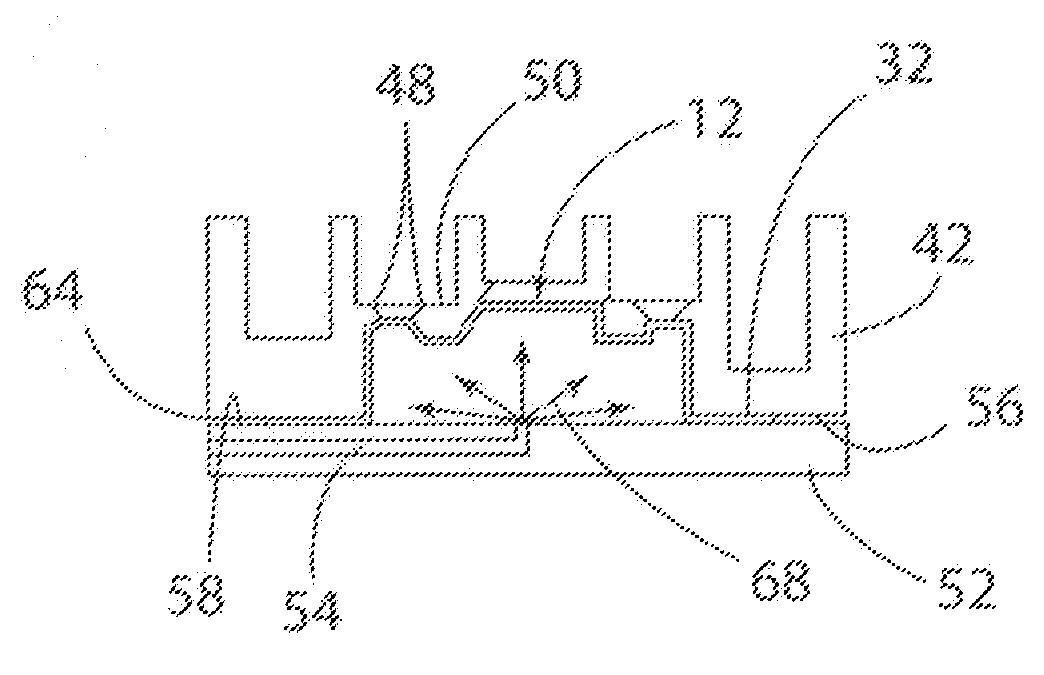
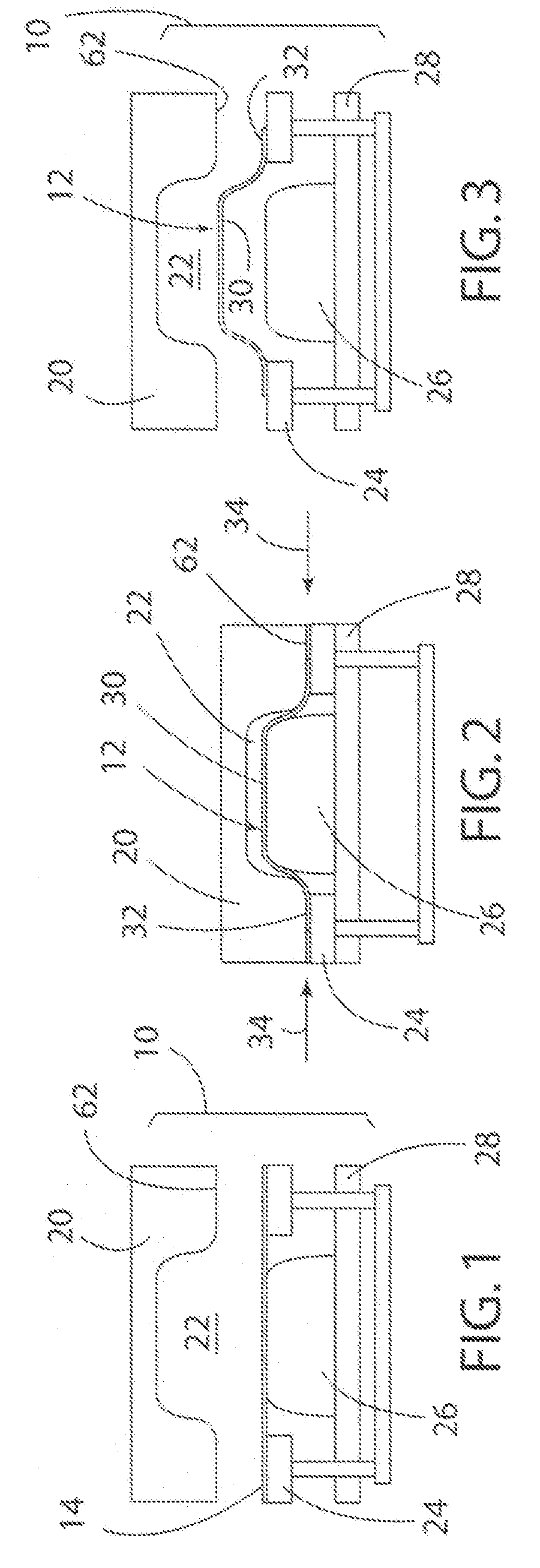
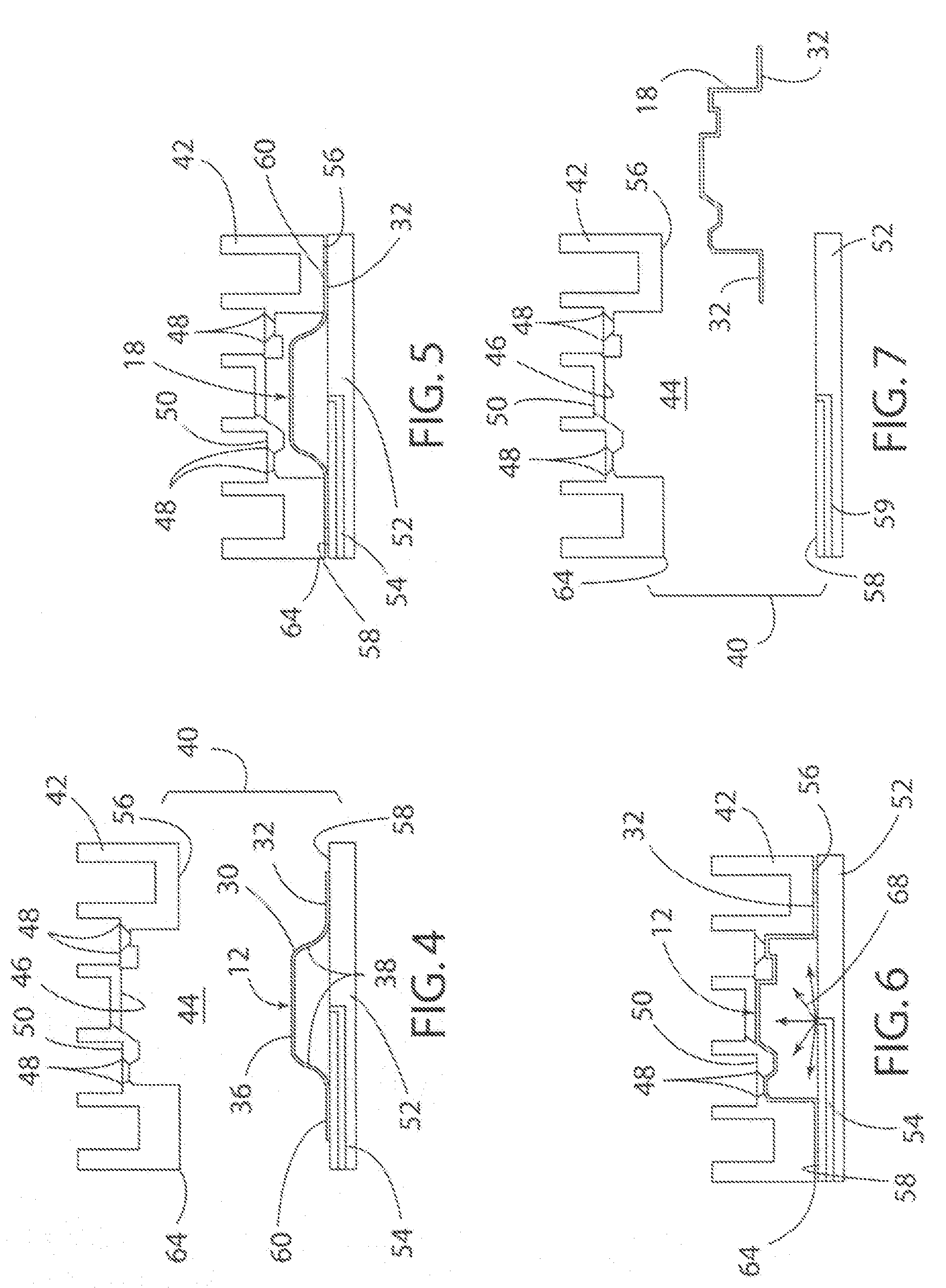
[0022]Referring now to the drawings, FIGS. 1-3 schematically illustrate a double-action draw die 10 used to create a preform 12 from a blank 14 according to a first stage of the present invention. FIGS. 4-7 schematically illustrate a second stage of the present invention using a superplastic forming tool 40 to complete the forming process on the preform 12 to create a finished workpiece 18. Typically, the process of the present invention is utilized with a blank 14 made of a lightweight sheet material, including a sheet of material formed of various aluminum and magnesium alloys. As shown in FIG. 1, the draw die 10 includes an upper die member 20 having a die cavity 22, a blank holder 24 and a punch 26 located on a lower die platen or member 28. Prior to beginning the forming process the draw die 10 is placed in a dual or double-action press (not shown) that operates to move the blank holder 24 independent of the punch 26.

[0023]A first step in the forming process is to place or load...


PUM

PropertyMeasurementUnit
temperatureaaaaaaaaaa
gas pressureaaaaaaaaaa
thicknessaaaaaaaaaa

Abstract

A sheet metal forming process and apparatus using both a mechanical forming step and a superplastic forming step. The mechanical forming step includes using a double-action draw die to create a preform. The preform is then transferred to a superplastic forming tool that uses a superplastic forming process to complete the forming process and create a finished workpiece. Using the mechanical forming step enables rapid creation of a preform having a geometry that reduces overall forming time and provides the ability to draw in additional material to reduce part thinning.

Description

CROSS-REFERENCE TO RELATED APPLICATIONS[0001]Not Applicable.BACKGROUND OF THE INVENTION[0002]1. Field of the Invention[0003]The present invention relates generally to material forming; and more particularly, to a method for forming a metal sheet.[0004]2. Description of Related Art[0005]Various methods are known for forming a metal sheet. One method involves a draw process wherein a punch pulls a portion of the metal sheet through a shaped die. During the process, the metal sheet typically undergoes a reduction or change in the cross-sectional area or wall thickness of the sheet. Such processes are typically limited by the material's ability to be strained past its rupture point. Thus, depending upon the complexity of the part, the forming stresses on the metal sheet during the forming process may result in metal failure or fatigue and correspondingly an unusable or scrap part.[0006]Superplastic forming (SPF) is a process that takes advantage of a material's superplasticity or abilit...

Claims


Application Information

Patent Timeline
Patent Type & Authority Applications(United States)
IPC IPC(8): B21D35/00
CPCB21D26/021B21D35/00B21D26/055B21D26/02
Inventor LUCKEY, S. GEORGEFRIEDMAN, PETER A.
Owner FORD GLOBAL TECH LLC
Why Eureka
Try Eureka