Dry Powder Inhalers that Inhibit Agglomeration, Related Devices and Methods

a technology of dry powder and inhaler, which is applied in the field of dry powder inhalers, can solve the problems of poor flow, unsatisfactory impact on the performance of dpi, and non-uniform dispersion, and achieve the effect of facilitating the deagglomeration of dry powder

Active Publication Date: 2008-06-05
ORIEL THERAPEUTICS INC
View PDF43 Cites 47 Cited by
  • Summary
  • Abstract
  • Description
  • Claims
  • Application Information

AI Technical Summary

Benefits of technology

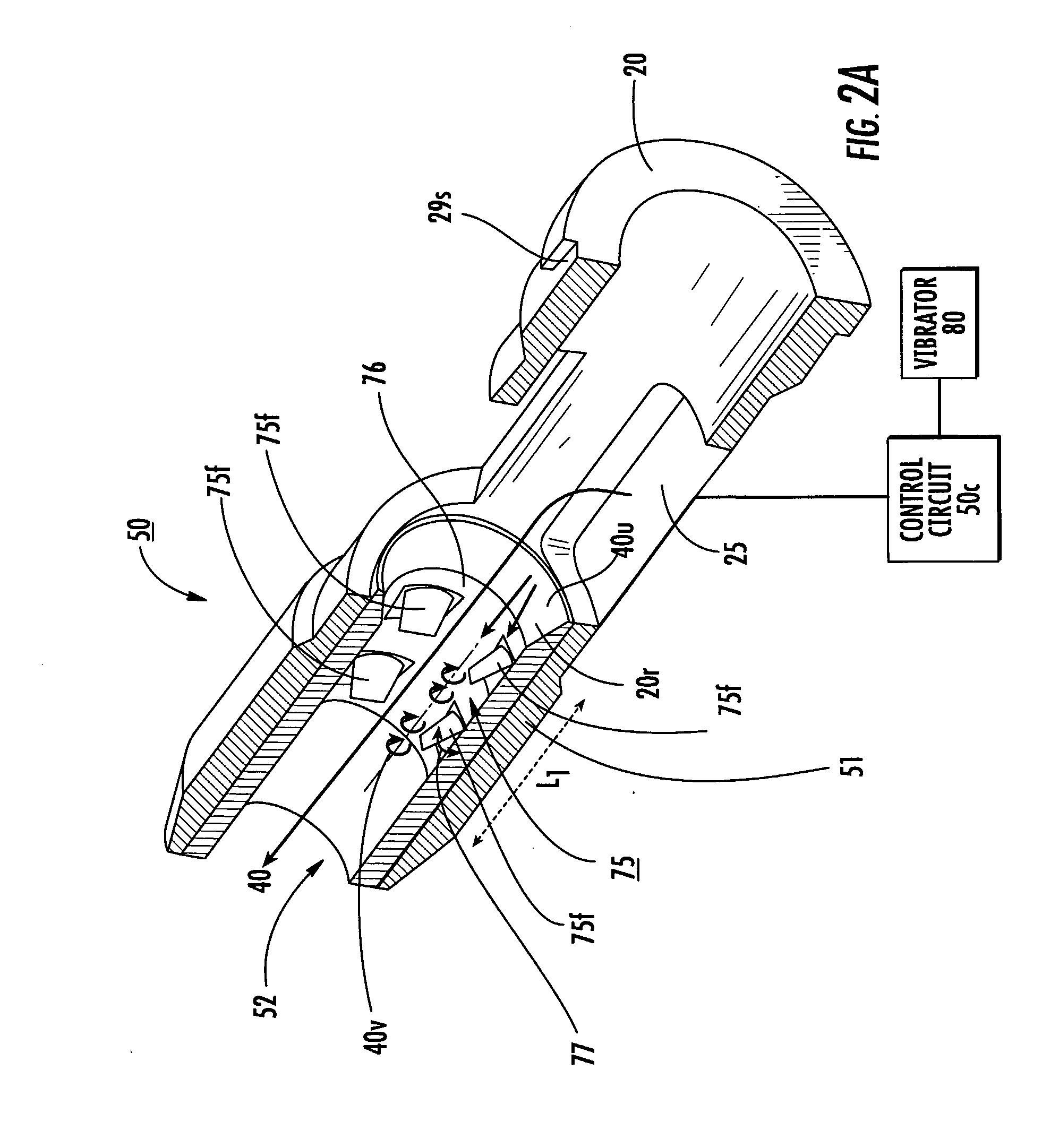
[0025]Some dry powder inhalers include: (a) an inhaler body with an inspiratory flow path therein; and (b) at least one mesh body residing in the inspiratory flow path. The at least one mesh body having a pattern of shapes that define two edges that meet at a point, the mesh body extending across at least a major portion of the inspiratory flow path to facilitate deagglomeration of dry powder as the dry powder flows through the mesh in response to inspiratory effort by a user.

Problems solved by technology

A number of obstacles can undesirably impact the performance of the DPI.
For example, the small size of the inhalable particles in the dry powder drug mixture can subject them to forces of agglomeration and / or cohesion (certain types of dry powders are susceptible to agglomeration, which is typically caused by particles of the drug adhering together), which can result in poor flow and non-uniform dispersion.
However, separation of the drug from the excipient, as well as the presence of agglomeration, can require additional inspiratory effort, which, again, can impact the stable dispersion of the powder within the air stream of the patient.
Unstable dispersions may inhibit the drug from reaching its preferred deposit / destination site and can prematurely deposit undue amounts of the drug elsewhere.
Further, some dry powder inhalers can retain a significant amount of the drug within the device, which can be especially problematic over time.

Method used


Image

  • Dry Powder Inhalers that Inhibit Agglomeration, Related Devices and Methods
  • Dry Powder Inhalers that Inhibit Agglomeration, Related Devices and Methods
  • Dry Powder Inhalers that Inhibit Agglomeration, Related Devices and Methods

Examples


examples

[0166]FIG. 30 is a graph illustrating the percentage of FPF emitted as a function of resistance (sqrt[cm H2O]) / lpm) (where “lpm” means “liters per minute”) taken under transient flow conditions and plotted for various shapes of fins and mesh configurations described herein with a dry powder formulation of a certain dose amount (taken at 60 lpm, with no vibratory signal). It is noted that the design numbers used in FIGS. 30 and 31 correspond to each other. In addition, the shapes and designs labeled in FIGS. 30 and 31 have been described above in the specification. However, the design numbers used in the graph of FIG. 30 and the table of FIG. 31 do not necessarily represent or correspond to the design numbers or shape numbers (or order) of the fins or mesh previously described above. The same dose amount, type of dry powder and air path size was used to obtain the data shown in FIG. 30.

[0167]It is anticipated that different fin and / or mesh configurations may be used for different for...


PUM

PropertyMeasurementUnit
areaaaaaaaaaaa
widthaaaaaaaaaa
lengthaaaaaaaaaa

Abstract

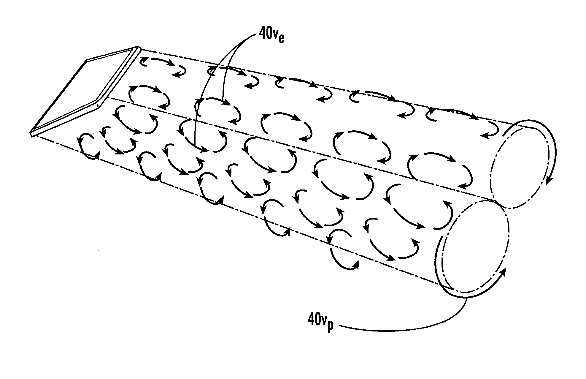
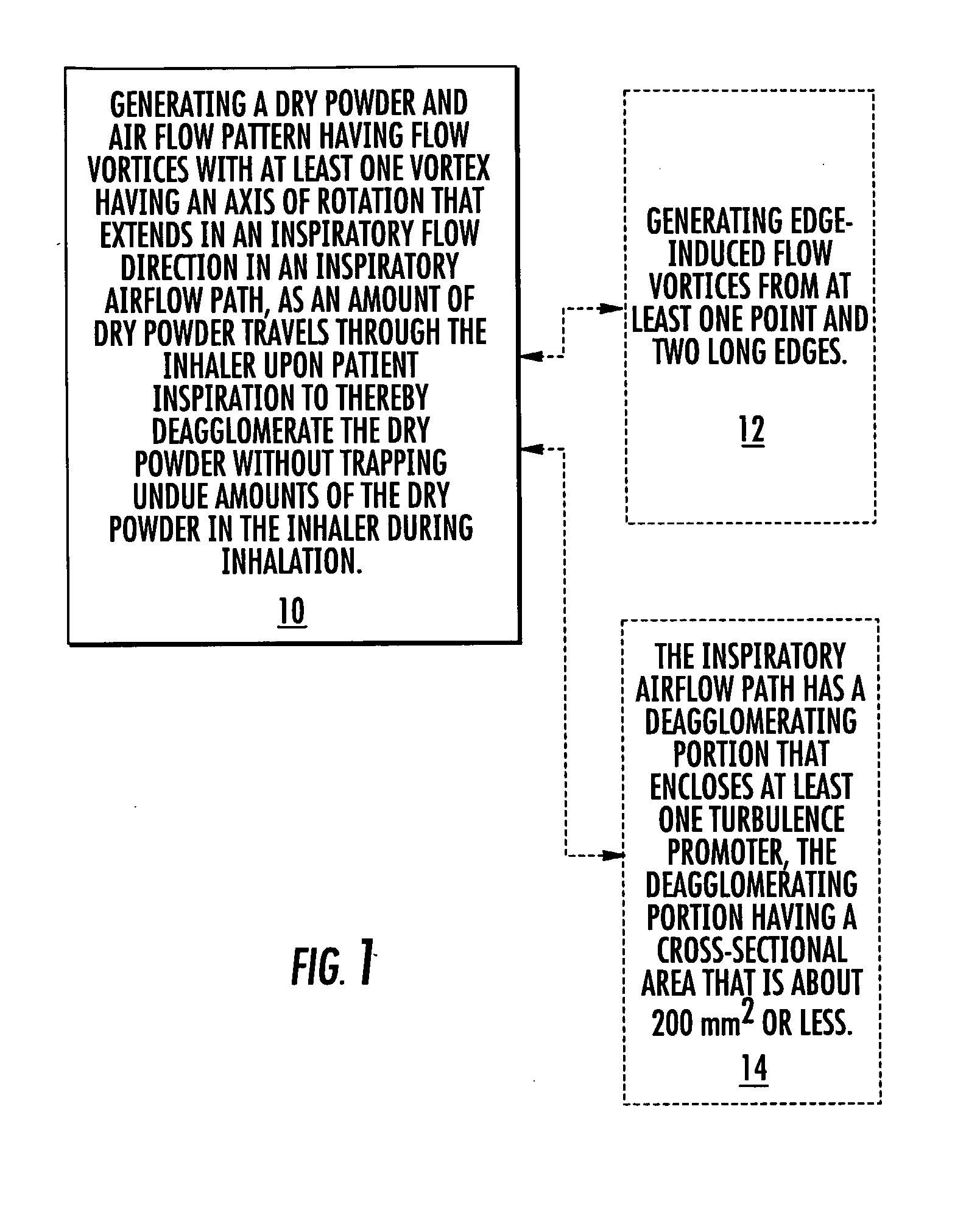
The disclosure describes methods and inhalers that deagglomerate dry powder using inspiratory effort of a user of an inhaler. Inhaler fin and mesh configurations are described that facilitate deagglomeration. At least in steady state conditions, a dry powder and airflow pattern can be generated having turbulence with flow vortices, some of which may have a vortex having an axis of rotation that extends in an inspiratory flow direction while others may have a vortex that is substantially orthogonal to the inspiratory flow direction in an inspiratory airflow path, as an amount of dry powder travels through the inhaler to thereby deagglomerate the dry powder without trapping undue amounts of the dry powder during inhalation.

Description

RELATED APPLICATIONS[0001]This application claims the benefit of priority from U.S. Provisional Patent Application Ser. No. 60 / 609,485 filed Sep. 13, 2004, the contents of which are hereby incorporated by reference as if recited in full herein.FIELD OF THE INVENTION[0002]The present invention relates to drug containment and / or dispensing systems suitable for dry powders formulated for delivery as inhalant aerosols.BACKGROUND OF THE INVENTION[0003]Dry powder inhalers (DPIs) represent a promising alternative to pressurized pMDI (pressurized meted dose inhaler) devices for delivering drug aerosols without using CFC propellants. See generally, Crowder et al., 2001: an Odyssey in Inhaler Formulation and Design, Pharmaceutical Technology, pp. 99-113, July 2001; and Peart et al., New Developments in Dry Powder Inhaler Technology, American Pharmaceutical Review, Vol. 4, n. 3, pp. 37-45 (2001). Typically, the DPIs are configured to deliver a powdered drug or drug mixture that includes an exc...

Claims


Application Information

Patent Timeline
Patent Type & Authority Applications(United States)
IPC IPC(8): A61M15/00B29C39/00
CPCA61M15/0086A61M2202/064A61M2205/3569A61M2205/3584A61M2205/3592Y10T29/49826B01F5/0619B01F2005/0636A61M15/0091A61M15/001A61M2206/14A61M15/008A61M15/0081A61M15/0083B01F25/43161B01F25/431971
Inventor KING, MICHAELWARDEN, JEFFREY ALANLOPATH, PATRICK D.LAROCHE, RICHARD D.
Owner ORIEL THERAPEUTICS INC
Why Eureka
Try Eureka