Advanced carbon dioxide fuel tank inerting system

a carbon dioxide fuel tank and inerting system technology, applied in the direction of packaging, liquid handling, transportation and packaging, etc., can solve the problems of nitrogen gas not supporting fuel vapor oxidation, significant safety hazards above the fuel,

Inactive Publication Date: 2008-06-05
HONEYWELL INT INC
View PDF11 Cites 113 Cited by
  • Summary
  • Abstract
  • Description
  • Claims
  • Application Information

AI Technical Summary

Problems solved by technology

The combination of fuel vapor and air existing in fuel tank ullage space (empty space above the fuel) can represent a significant safety hazard.
For example, the National Transportation Safety Board concluded that the probable cause of the loss in 1996 of TWA flight 800 with all passengers and crew was an explosion of the center wing fuel tank, resulting from ignition of the flammable fuel / air mixture in the tank.
The FAA report concluded that this type of accident represents a serious threat and that fuel tank inerting should be used to prevent future events of this type.
Nitrogen gas does not support fuel vapor oxidation and represents the current best method for on-board generation of an inert gas.
The liquid jet fuel used in aviation, however, typically contains a substantial amount of sulfur-containing components, which can lead, for example, to problems such as corrosion of metal components in the inerting system.
Jet fuel has a very low vapor pressure, however, at some of the conditions leading to low temperatures encountered in the fuel tank of aircraft.
In particular the temperature in the fuel tank may be very low during descent after a long cruise at high altitude.

Method used


Image

  • Advanced carbon dioxide fuel tank inerting system
  • Advanced carbon dioxide fuel tank inerting system
  • Advanced carbon dioxide fuel tank inerting system

Examples


Embodiment Construction

[0015]The following detailed description is of the best currently contemplated modes of carrying out the invention. The description is not to be taken in a limiting sense, but is made merely for the purpose of illustrating the general principles of the invention, since the scope of the invention is best defined by the appended claims.

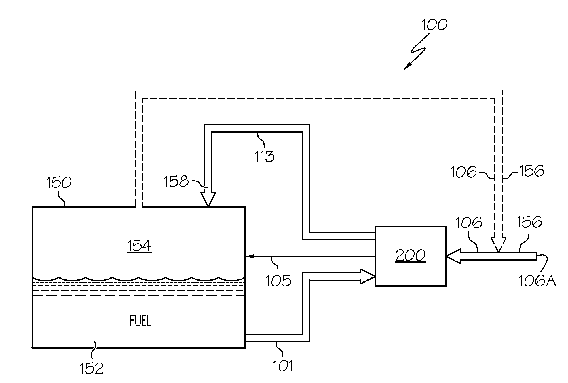
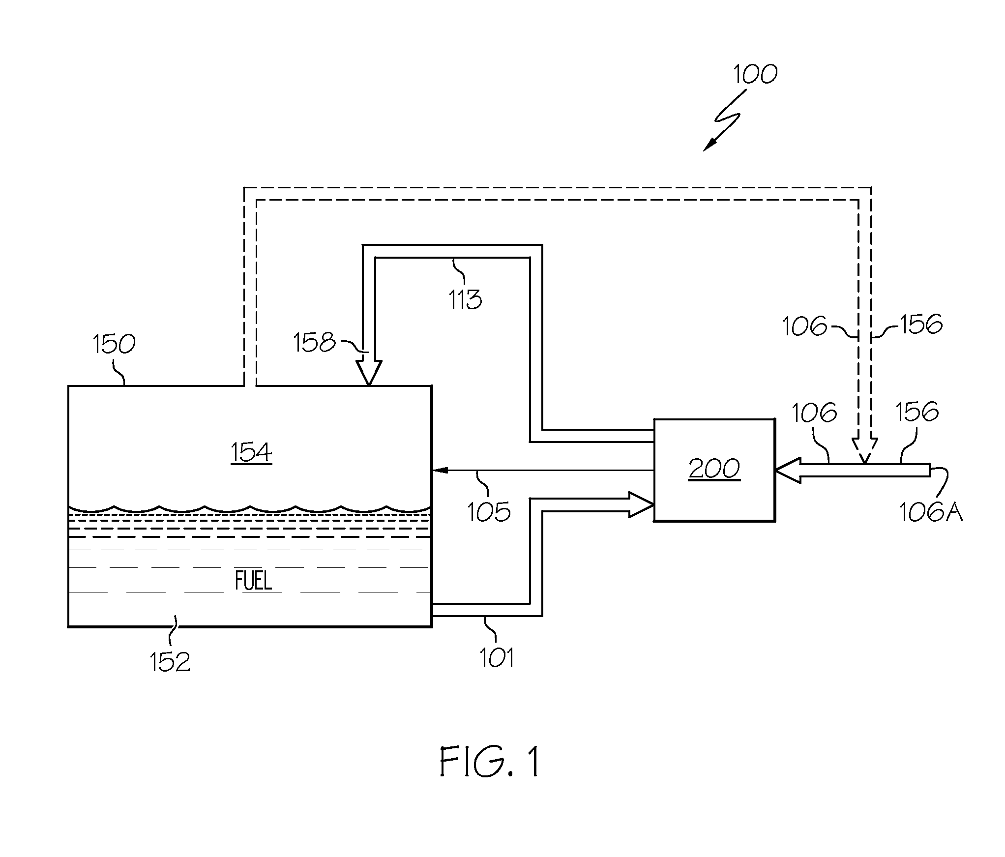
[0016]Broadly, embodiments of the present invention provide fuel tank inerting systems and methods for maintaining an inert, i.e., non-flammable, gas in the ullage space of a fuel tank containing a hydrocarbon fuel such as aviation jet fuel. Embodiments may be especially useful for commercial and military aircraft, and may also be applicable to fuel tanks for any type of vehicle—such as automobiles, trucks, and ships—where fire safety may be of concern. Embodiments of the present invention may exhibit the following operating principles: a) Fuel vapor generally is not explosive under conditions found in an aircraft in a volume in which the concentration ...


PUM


Abstract

An onboard inert gas generation system includes an evaporator comprising a vessel that receives a hydrocarbon fuel from a fuel tank, separates vapor fuel components from liquid fuel components, establishes a nearly constant fuel vapor composition, and outputs the fuel vapor to be mixed with air prior to combusting the fuel vapor and air mixture in a catalytic reactor. Water is separated from the inert gas produced and the inert gas is introduced into the ullage space of the fuel tank to prevent or reduce possible hazardous conditions in the fuel tank.

Description

BACKGROUND OF THE INVENTION[0001]The present invention generally relates to hydrocarbon fuel tank safety systems and, more particularly, to maintaining inert gas in the ullage space of a fuel tank containing a hydrocarbon fuel such as aviation jet fuel.[0002]The combination of fuel vapor and air existing in fuel tank ullage space (empty space above the fuel) can represent a significant safety hazard. For example, the National Transportation Safety Board concluded that the probable cause of the loss in 1996 of TWA flight 800 with all passengers and crew was an explosion of the center wing fuel tank, resulting from ignition of the flammable fuel / air mixture in the tank. The fuel vapor suddenly reacted with great violence with the oxygen present in the ullage space. The FAA report concluded that this type of accident represents a serious threat and that fuel tank inerting should be used to prevent future events of this type.[0003]One approach to fuel tank inerting is to introduce nitro...

Claims


Application Information

Patent Timeline
Patent Type & Authority Applications(United States)
IPC IPC(8): B65B31/00
CPCB64D37/32
Inventor JOHNSON, RUSSELL W.ZAKI, REHANYATES, STEPHEN F.
Owner HONEYWELL INT INC
Why Eureka
Try Eureka