Discharge cell for ozonizer

a technology of ozonizer and discharge cell, which is applied in the direction of electrical discharge ozone preparation, oxygen/ozone/oxide/hydroxide, etc., can solve the problems of many problems in the functional film formed in such a manner, and achieve the effect of preventing a decrease of ozone concentration

Inactive Publication Date: 2008-06-05
SUMITOMO PRECISION PROD CO LTD
View PDF3 Cites 4 Cited by
  • Summary
  • Abstract
  • Description
  • Claims
  • Application Information

AI Technical Summary

Benefits of technology

[0034]Because a functional substance for preventing a decrease of the ozone concentration is fixed on the surface of the dielectric using a baking fixing agent in the discharge cell for an ozonizer in the present invention, a highly concentrated functional substance that is difficult to be contained in the dielectric can be made to exist on the surface of the dielectric, and the cell is superior in the effect of preventing a decrease of the ozone concentration by the functional substance. Because of this, the ability of the ozonizer can be brought to full without adding nitrogen into oxygen gas or with adding a small amount of nitrogen. On top of that, because the dielectric is not processed, a less expensive product on the market and a general-purpose material can be used as the dielectric, and a cell cost can be kept low. Furthermore, being different from the formation of the functional film with flame spraying and welding, because film fixing strength is high, peeling and falling-out can be prevented during a cell operation. Further, a film forming coat is less expensive, and from this respect, a cell cost can be kept low. Furthermore, film thickness control is easy, formation of a very thin film with a thickness of a few μm is possible, and there is no risk of having a harmful influence on a rib for forming a discharge gap.

Problems solved by technology

However, it is as described above that the functional film formed in such a manner has many problems.

Method used


Image

  • Discharge cell for ozonizer
  • Discharge cell for ozonizer

Examples


examples

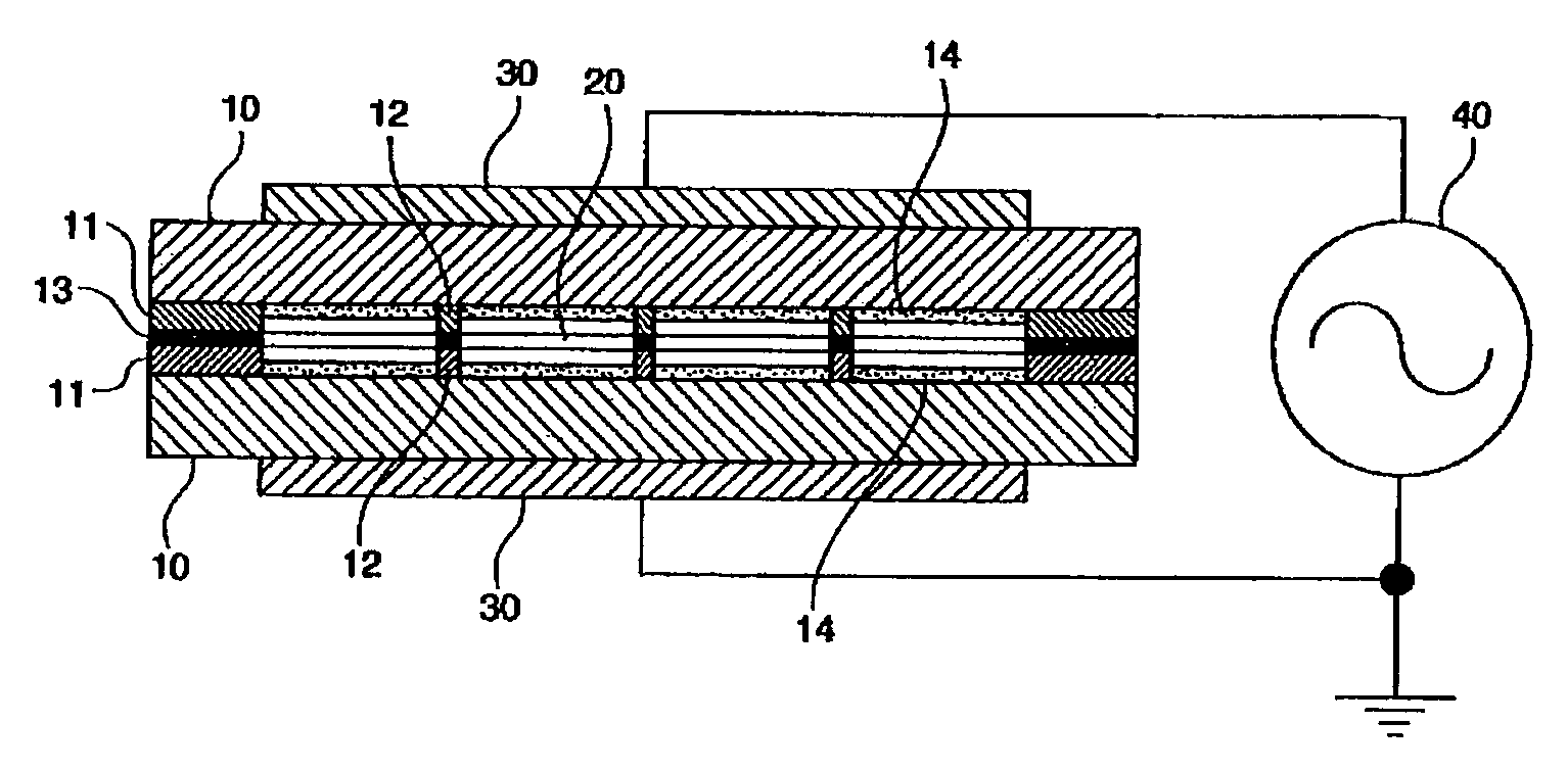
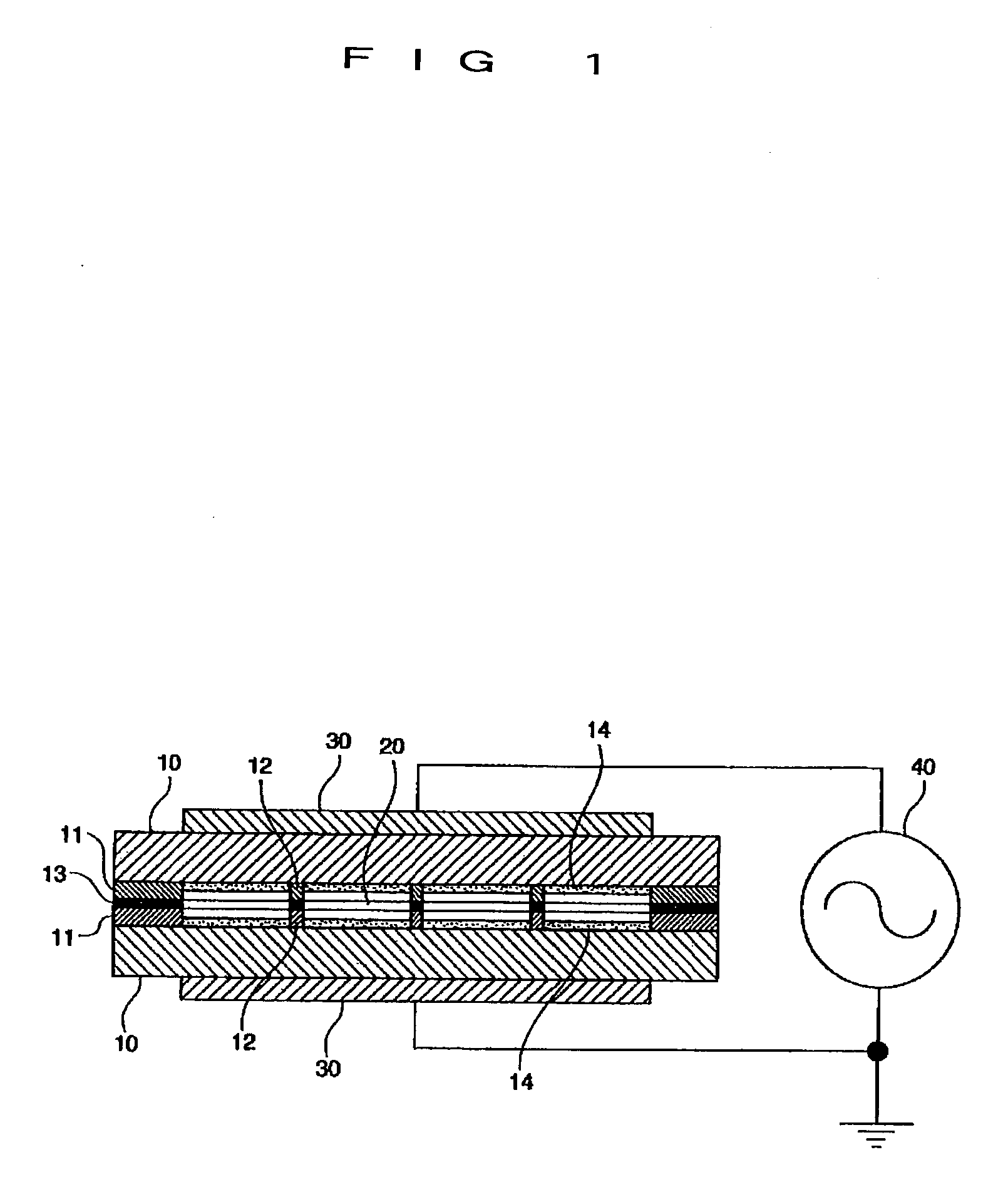
[0046]Next, an advantage of forming the functional films 14, 14 on the opposing surfaces of the dielectrics 10, 10 is explained using a case where the catalytic substance in the functional films 14, 14 is TiO2 and NiO.

[0047]In the above-described discharge cell for an ozonizer, a high purity alumina powder sintered substrate with a purity of 99.5% available from the market was used as the dielectric. The thickness is 0.5 mm. The area of the discharge gap is 100 cm2, and the gap amount is 0.1 mm (100 μm). Oxygen gas with a purity of 99.99% or more was supplied as a raw material gas with a flow rate of 1 L / min and a pressure of 0.2 MPa. Power supply was set to be the maximum power of the ozonizer. The ozone concentration of the produced ozone gas was 10 g / m3 (N) and was extremely low compared with the objective ozone concentration 200 g / m3 (N).

[0048]0.5 vol % of nitrogen gas was added to the above-described high purity oxygen gas. However, the ozone concentration was still 10 g / m3 (N)...


PUM

PropertyMeasurementUnit
particle sizeaaaaaaaaaa
thicknessaaaaaaaaaa
viscosityaaaaaaaaaa

Abstract

Decrease in the ozone concentration that becomes a problem when high purity oxygen is used as a raw material gas is prevented. A high purity alumina substrate having a high screen degree is used as a dielectric. A catalytic substance to hinder the decrease of the ozone concentration is fixed on the surface of the alumina substrate as the dielectric by a baking fixing agent. The baking fixing agent is a glass that becomes a paste form that is capable of powder kneading the catalytic substance and attaching to the surface of the dielectric, fixes the catalytic substance on the surface of the dielectric by hardening by baking, and shows ozone resistance and sputtering resistance under the production of ozone in the discharge gap, and forms a functional film containing a large amount of the catalytic substance and is stable on the surface of the dielectric.

Description

BACKGROUND OF THE INVENTION[0001]1. Field of the Invention[0002]The present invention relates to a discharge cell used in a discharge type ozonizer, and in more detail, relates to a discharge cell for an ozonizer that is capable of bringing out the maximum ability of the ozonizer even in the case where nitrogen is not added or a small amount of nitrogen is added into the raw material gas.[0003]2. Description of the Related Art[0004]Discharge cells used in a discharge type ozonizer, called as an ozonizer, are roughly divided into a plate type and a tube type. Each of the discharge cells have a pair of electrodes arranged with a gap therebetween, and have a configuration in which a dielectric is arranged between the electrodes so as to contact at least one of the electrode surfaces of the pair of electrodes to form a discharge gap between the electrodes. Ozone gas is produced by circulating a raw material gas such as oxygen in the discharge gap with a condition in which a silent disch...

Claims


Application Information

Patent Timeline
Patent Type & Authority Applications(United States)
IPC IPC(8): C25B9/00
CPCC01B13/11C01B2201/34C01B2201/12
Inventor MATSUNO, TAKASHI
Owner SUMITOMO PRECISION PROD CO LTD
Why Eureka
Try Eureka