Eureka AIR delivers breakthrough ideas for toughest innovation challenges, trusted by R&D personnel around the world.

Light-weight vacuum chamber and appalications thereof

a vacuum chamber and light-weight technology, applied in the field of vacuum chambers, can solve the problems of high weight in such an environment, buckling instability of traditional vacuum chambers, and heavy design, and achieve the effect of reducing the potential modes of buckling instability and lighter vessels

Inactive Publication Date: 2008-06-05
FLORIDA STATE UNIV RES FOUND INC
View PDF9 Cites 3 Cited by
  • Summary
  • Abstract
  • Description
  • Claims
  • Application Information

AI Technical Summary

Benefits of technology

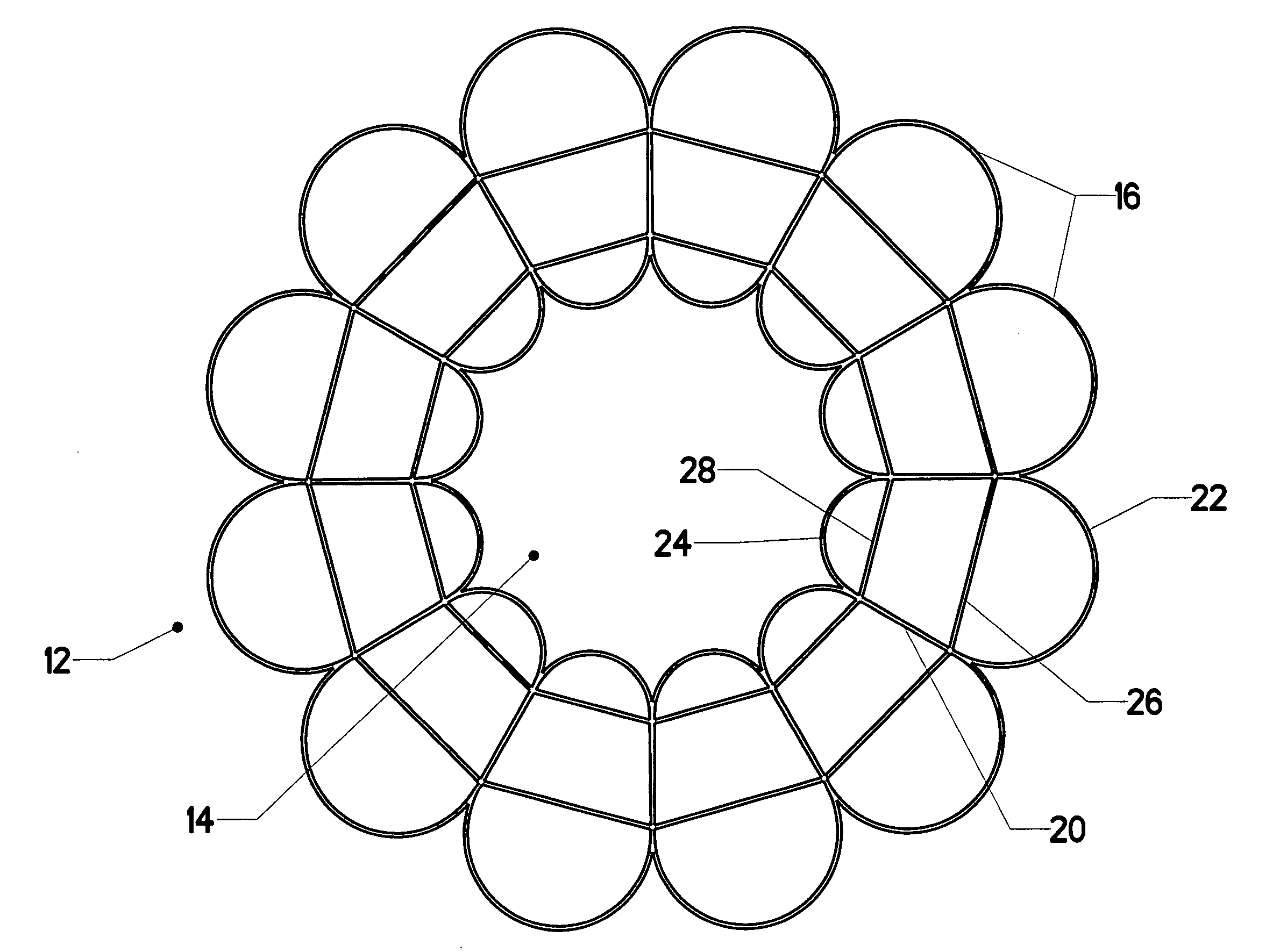
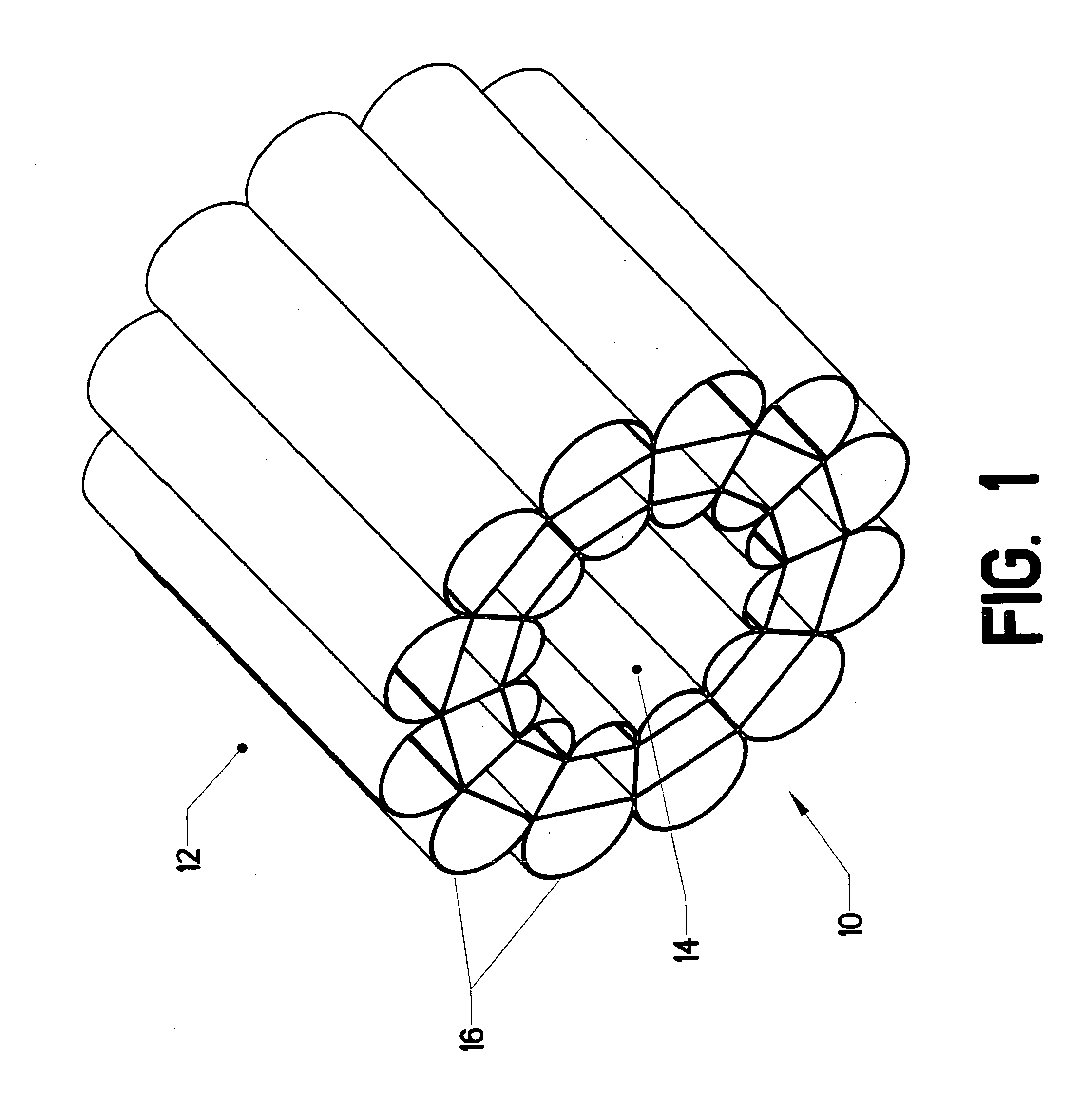
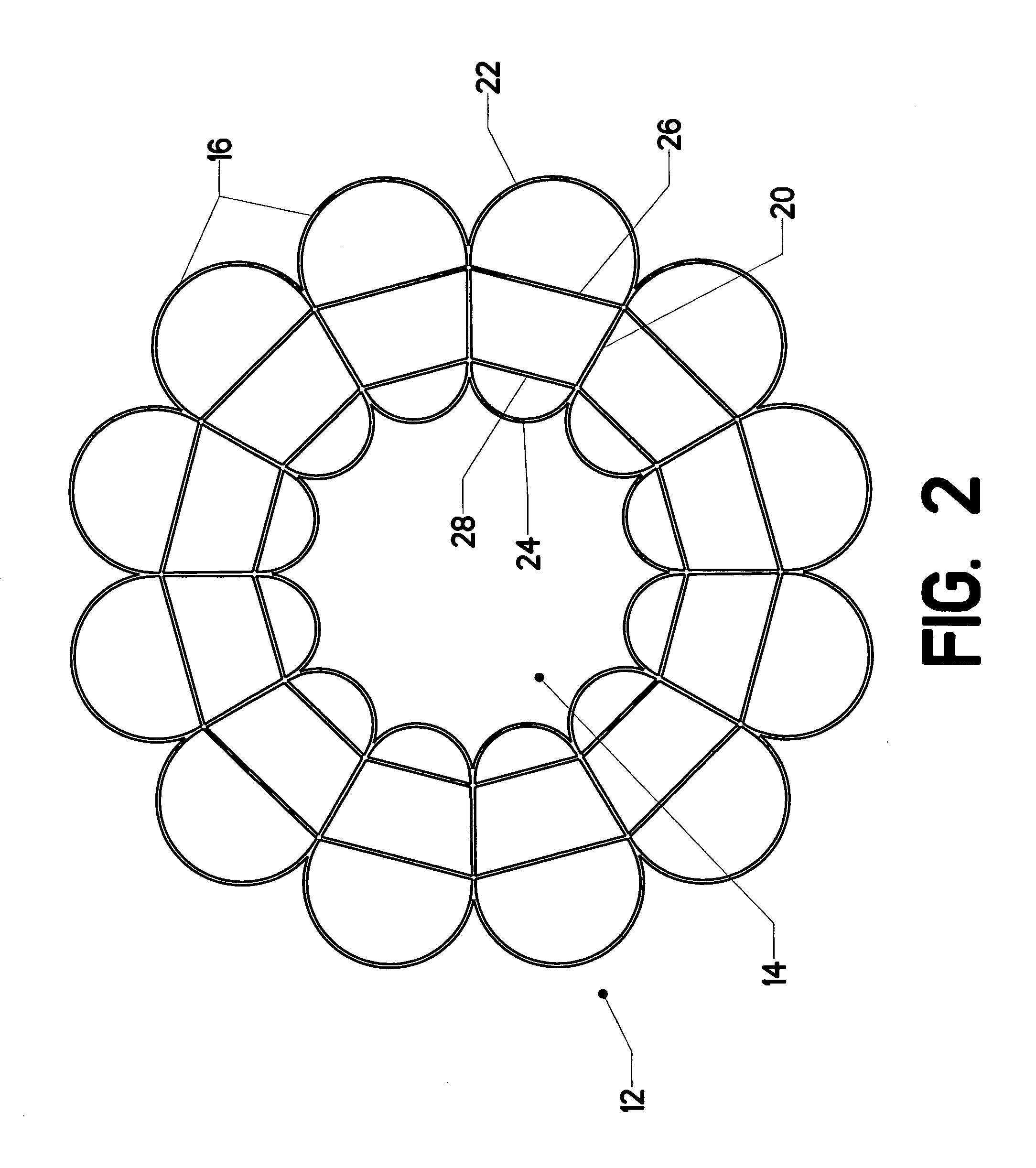
[0032]The present invention comprises a vacuum chamber with an innovative wall structure. Instead of a conventional homogenous wall structure, the invention uses an array of internally-pressurized, thin-walled cells to contain an enclosed volume. The walls are arranged so that when a vacuum is present in the enclosed volume, the cell walls are placed in tension. In this way the potential modes of buckling instability are substantially reduced. The result is a much lighter vessel compared to a conventional homogenous wall vessel of similar strength.

Problems solved by technology

Traditional designs have been quite heavy.
However, for mobile chambers, weight can be a very significant concern.
The weight associated with traditional vacuum chambers can be highly significant in such an environment.
Such a chamber typically fails well before the ultimate compressive limit of the material used, since the chamber fails by buckling.
Compressive forces tend to produce an inherently unstable situation.
Of course, one must also consider deformation failure (buckling).
Thus, one can conclude that it is not possible to construct a positively buoyant vacuum chamber using a conventional thin-walled cylinder (at least using any materials presently known).
Obviously, the thin-walled cylinder approach cannot achieve this goal.
Because a cylinder under external pressure has twice as much compressive stress around its circumference compared to its long axis, it is acceptable (if using an isotropic building material) to lose 50% of the strength in the axial direction through changes in geometry (like corrugation) but it is undesirable to lose any strength in the circumferential direction.
For anisotropic materials, this technique is less effective because the fibers of the matrix are originally placed to provide strength only in the direction it is needed and thus any alteration of geometry that reduces strength in any direction (for an optimized fiber orientation) immediately requires weight increase.
Corrugation helps, but it cannot possibly achieve buoyancy at atmospheric pressure.
Even the use of a complex “corrugation upon corrugation” approach—where the corrugated profile is itself corrugated—cannot achieve buoyancy.
Unfortunately, the inclusion of such internal pre-tensioned members immediately adds structural weight.
However, structural details would be very small and manufacture would be nearly impossible.

Method used


Image

  • Light-weight vacuum chamber and appalications thereof
  • Light-weight vacuum chamber and appalications thereof
  • Light-weight vacuum chamber and appalications thereof

Examples


Embodiment Construction

[0100]The basic structure of the lightweight vacuum chamber will be described, followed by an explanation of the theoretical principles underlying its construction. Possible applications for the chamber will then be disclosed.

[0101]FIG. 1 shows vacuum chamber 10. Its “wall” is defined by a radial array of joined cells 16. These cells separate contained volume 14 from the surrounding atmosphere 12. The view shows only a portion of a complete chamber. Obviously, the open ends must be capped off in order to create a vacuum within contained volume 14. The cells in this example are linear, meaning that they have a fixed cross section projected in a direction which is parallel to the central access of the vacuum chamber.

[0102]FIG. 2 is an elevation view of the same structure. Each cell 16 is defined by an enclosing cell wall. This cell wall can be divided into several distinct portions. These are: outer arcuate portion 22, inner arcuate portion 24, and two linear conjoined portions 20 (on...


PUM

PropertyMeasurementUnit
Pressureaaaaaaaaaa
Pressureaaaaaaaaaa
Pressureaaaaaaaaaa

Abstract

A vacuum chamber with an innovative wall structure. Instead of a conventional homogenous wall structure, the invention uses an array of internally-pressurized, thin-walled cells to contain an enclosed volume. The walls are arranged so that when a vacuum is present in the enclosed volume, the cell walls are placed primarily in tension. In this way the likelihood of buckling instability is substantially reduced. The result is a much lighter vessel compared to a conventional homogenous wall vessel of similar strength.

Description

BACKGROUND OF THE INVENTION[0001]1. Field of the Invention[0002]This invention relates to the field of vacuum chambers. More specifically, the invention comprises a novel construction for a vacuum chamber in which the wall members are subjected primarily to tensile forces. Applications for the vacuum chamber are also disclosed.[0003]2. Description of the Related Art[0004]Vacuum chambers have been in existence for many years. They generally have thick and strong walls, so that they can resist the compressive forces exerted by the surrounding atmosphere. The walls must resist simple compressive forces (hoop and axial forces), and must generally be thick enough to prevent buckling. Those skilled in the art will know that buckling instability typically defines the failure limit of a vacuum chamber.[0005]Traditional designs have been quite heavy. For earth-bound vacuum chambers, weight is frequently not a concern. However, for mobile chambers, weight can be a very significant concern. Th...

Claims


Application Information

Patent Timeline
IPC IPC(8): B65D8/06
CPCF17C3/08Y02E60/321F17C2201/052F17C2201/054F17C2203/011F17C2203/0391F17C2203/0617F17C2203/0619F17C2203/0621F17C2203/0624F17C2203/0636F17C2203/0673F17C2221/012F17C2223/0153F17C2223/0161F17C2223/033F17C2270/01F24J2/055F24J2/5271Y02E10/47F17C2201/0147F24S20/80F24S10/45Y02E60/32
Inventor BARTON, SEAN ANDERSON
Owner FLORIDA STATE UNIV RES FOUND INC
Why Eureka
Eureka Blog
Learn More