Illumination device with semiconductor light-emitting elements
a technology of light-emitting elements and illumination devices, which is applied in the direction of printed circuit components, light and heating apparatuses, printed circuit manufacturing, etc., can solve the problems of insufficient use of light from light-emitting diodes, insufficient light extraction from light-emitting diodes, and insufficient brightness, so as to suppress the temperature rise of semiconductor light-emitting elements and efficiently extract light
- Summary
- Abstract
- Description
- Claims
- Application Information
AI Technical Summary
Benefits of technology
Problems solved by technology
Method used
Image
Examples
first embodiment
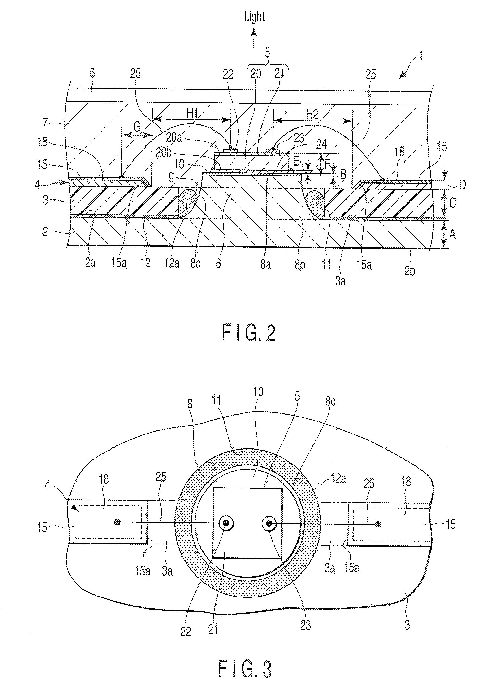
[0078]the present invention will now be described with reference to FIG. 1 to FIG. 5.
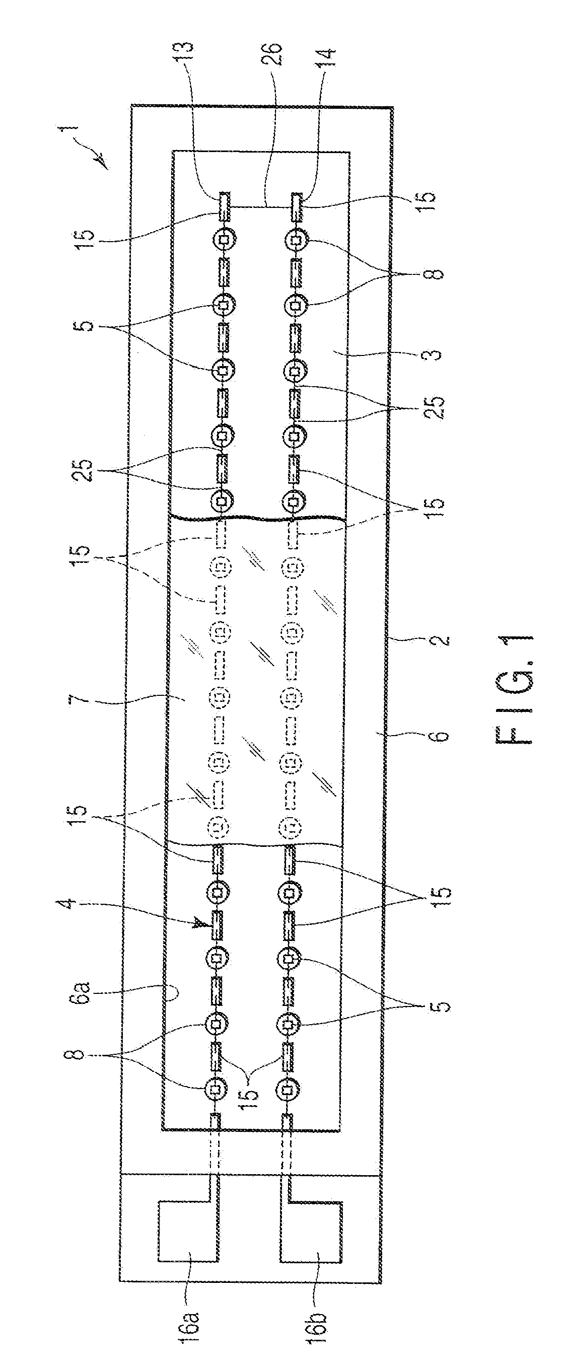
[0079]FIG. 1 discloses an illumination device 1 which constitutes, for example, an LED package. The illumination device 1 includes a base board 2, an insulator 3, a conductor 4, a plurality of semiconductor light-emitting elements 5, a reflector 6 and a sealing member 7.
[0080]The base board 2 has, for example, a rectangular shape in order to obtain a light emission area that is required by the illumination device 1. The material of the base board 2 should preferably be a metal with good heat radiation properties, such as copper or an aluminum alloy. As shown in FIG. 2, the base board 2 has a front surface 2a and a back surface 2b which is located opposite to the front surface 2a. A plurality of columnar projection portions 8 are integrally formed on the front surface 2a of the base board 2. The number of projection portions 8 corresponds to the number of semiconductor light-emitting elements 5.
[0081...
second embodiment
[0129]FIG. 6 shows the present invention. The second embodiment differs from the first embodiment with respect to the structure of the reflector 6. In the other structural aspects, the second embodiment is the same as the first embodiment. Thus, in the second embodiment, the structural parts common to those in the first embodiment are denoted by like reference numerals, and a description thereof is omitted.
[0130]As shown in FIG. 6, the reflector has a plurality of reflection holes 31 (only one of them being shown) which are associated with the semiconductor light-emitting elements 5. The semiconductor light-emitting element 5, which is bonded to the projection portion 8 of the base board 2, is individually disposed in the reflection hole 31. The reflection hole 31 is a taper hole with a diameter which gradually increases from the base board 2 in the light-extraction direction. The sealing member 7 is filled in each of the reflection holes 31. The sealing member 7 is continuously fil...
third embodiment
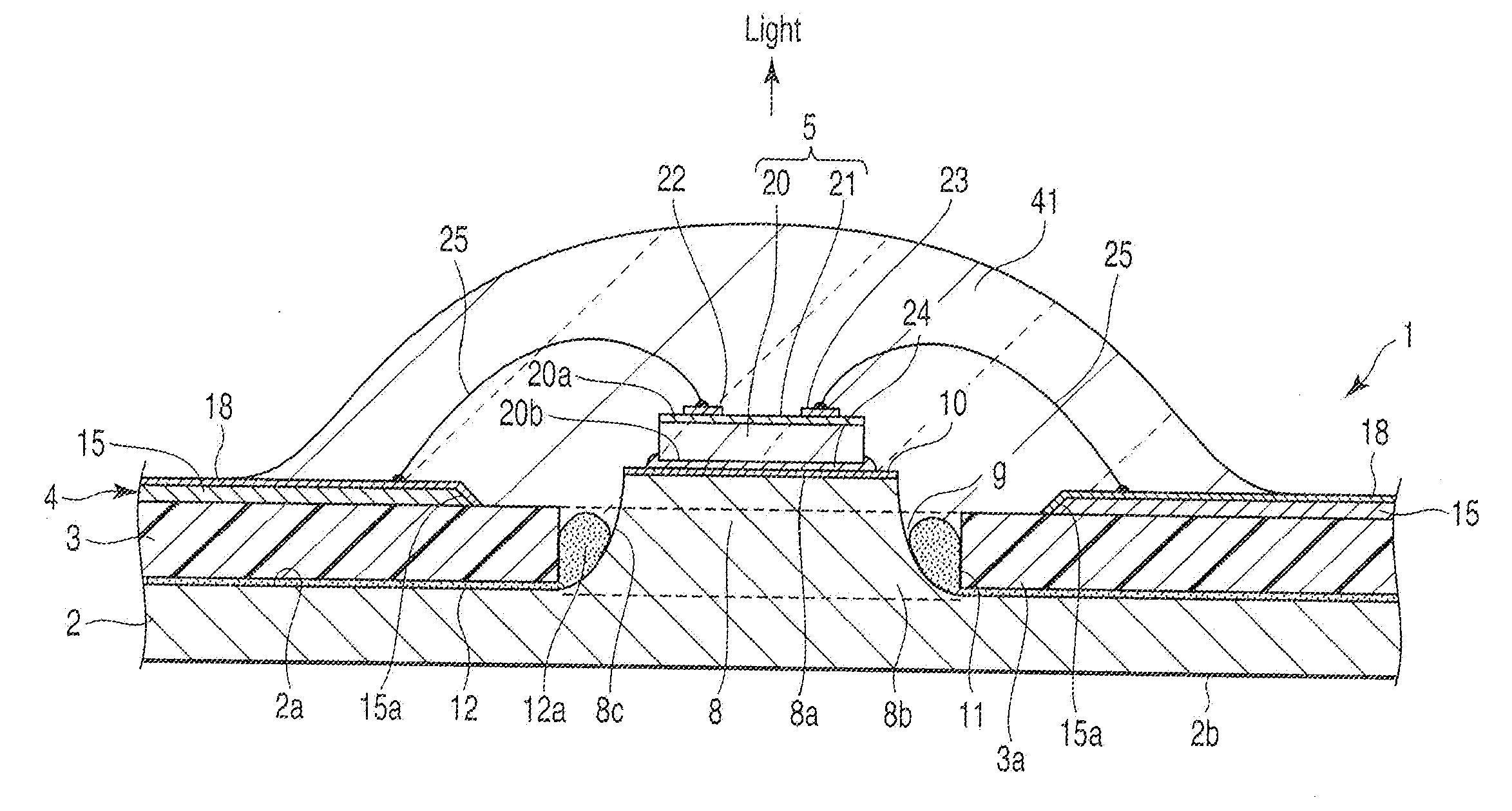
[0133]FIG. 7 shows the present invention.
[0134]The third embodiment differs from the first embodiment in that the reflector of the illumination device 1 is dispensed with. In the other respects, the structure of the illumination device 1 of the third embodiment is the same as in the first embodiment.
[0135]In the third embodiment, the semiconductor light-emitting element 5, which is bonded to the projection portion 8 of the base board 2, is individually sealed by a sealing member 41. The sealing member 41 is formed by dispensing a non-solidified resin on each of the semiconductor light-emitting element 5 from a dispenser (not shown). The non-solidified resin, after dispensed from the dispenser, is solidified in a hemispherical shape. The sealing member 41 includes a phosphor. The phosphor is uniformly dispersed in the sealing member 41. Further, the sealing member 41 is continuously filled in the gap g between the through hole 11 of the insulator 3 and the outer peripheral surface 8c...
PUM
 Abstract
Description
Claims
Application Information
 - R&D
- Intellectual Property
- Life Sciences
- Materials
- Tech Scout
- Unparalleled Data Quality
- Higher Quality Content
- 60% Fewer Hallucinations
Browse by: Latest US Patents, China's latest patents, Technical Efficacy Thesaurus, Application Domain, Technology Topic, Popular Technical Reports.
© 2025 PatSnap. All rights reserved.Legal|Privacy policy|Modern Slavery Act Transparency Statement|Sitemap|About US| Contact US: help@patsnap.com


