Device for controlling single-phase power conditioner for renewable energy system

a renewable energy system and control device technology, applied in the direction of emergency power supply arrangement, magnetic body, pulse technique, etc., can solve the problems of surge current/voltage, load requires electricity, and often occurs surge current/voltage, etc., to achieve better efficiency and output voltage waveform

Active Publication Date: 2008-06-05
IND TECH RES INST
View PDF7 Cites 44 Cited by
  • Summary
  • Abstract
  • Description
  • Claims
  • Application Information

AI Technical Summary

Benefits of technology

[0008]It is a primary object of the present invention to provide a control device for a single-phase power conditioner for a renewable energy system, thereby the renewable energy system is tied with the utility system to provide electricity when the utility system functions normally, otherwise the load consumes transferred power with negligible transfer time when one of the utility system and the renewable energy system does not provide electricity. In the present invention, the power conditioner provides better efficiency and output voltage waveform.

Problems solved by technology

However, the load requires electricity even when the renewable energy system or the utility power system is mal-functional.
In this grid-tied mode, the load consumes power from the power system.
However, during power transfer from the grid-tied mode to the standalone mode, a surge current / voltage often occurs.
Moreover, it often takes a considerable period of time for detection.
Similar to U.S. Patent Publication No. 20050006958, it takes a considerable period of time for power transfer, wherein a surge current / voltage often occurs.
Similarly, a surge current / voltage often occurs during power transfer when the power system is mal-functional.

Method used


Image

  • Device for controlling single-phase power conditioner for renewable energy system
  • Device for controlling single-phase power conditioner for renewable energy system
  • Device for controlling single-phase power conditioner for renewable energy system

Examples


Embodiment Construction

[0031]The present invention providing a control device for a single-phase power conditioner for a renewable energy system can be exemplified by the preferred embodiment as described hereinafter.

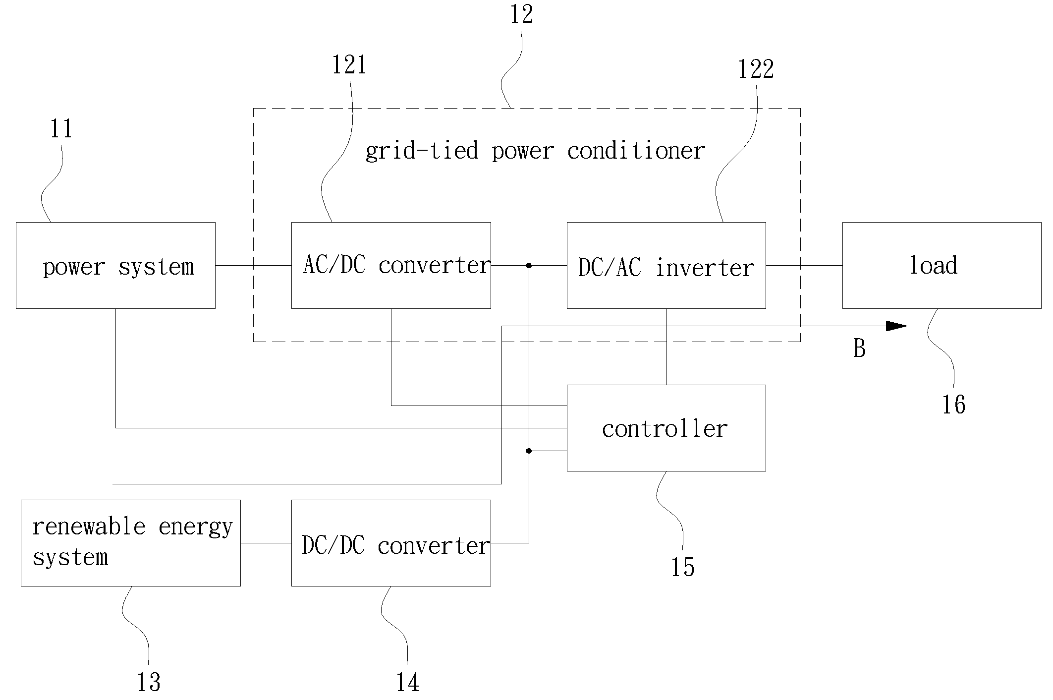
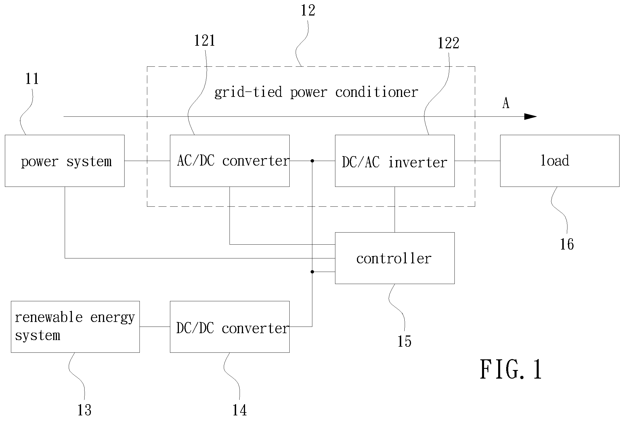
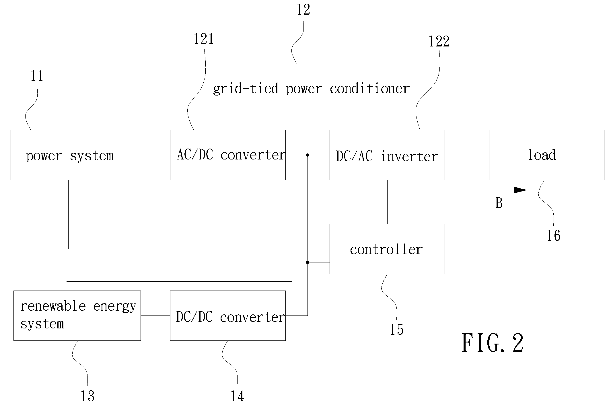
[0032]Please refer to FIG. 1, FIG. 2, FIG. 3 and FIG. 4, which show a device for controlling a single-phase power conditioner for a renewable energy system in a first, a second, a third and a fourth operation states, respectively, according to the present invention. The controlling device comprises a power system 11, a renewable energy system 13, a DC-to-DC converter 14, a grid-tied power conditioner 12, a controller (also referred to as a power transfer decider) 15 and a load 16. The grid-tied power conditioner 12 is a bi-directional power conditioner and comprises a DC-to-AC inverter 122 and an AC-to-DC converter 121. The power system 11 and the renewable energy system 13 are connected in parallel to the DC link by way of the grid-tied power conditioner 12 and the DC-to-DC converter 14, res...


PUM


Abstract

A device for controlling a single-phase power conditioner for a renewable energy system. The device comprises: a power system, providing alternating current (AC) utility power; a renewable energy system, using a natural resource so as to generate direct current (DC) power; a DC-to-DC converter, accepting the DC power generated by the renewable energy system so as to convert an input DC voltage of the DC power to an output DC voltage at a voltage level different from the DC input voltage; a grid-tied power conditioner, transforming voltage levels of the AC power and DC power; a controller, issuing a control signal for controlling the grid-tied power conditioner; and a load, consuming electricity by way of the grid-tied power conditioner.

Description

BACKGROUND OF THE INVENTION[0001]1. Field of the Invention[0002]The present invention generally relates to a device for controlling a single-phase power conditioner for a renewable energy system and, more particularly, to a control device for a single-phase power conditioner for a renewable energy system, thereby the renewable energy system is tied with the utility system to provide electricity when the utility system functions normally, otherwise the load consumes transferred power with negligible transfer time when one of the utility system and the renewable energy system does not provide electricity. In the present invention, the power conditioner provides better efficiency and output voltage waveform.[0003]2. Description of the Prior Art[0004]The distributed energy system and the renewable energy system are tied in parallel with the utility power system in practical uses. However, the load requires electricity even when the renewable energy system or the utility power system is ...

Claims


Application Information

Patent Timeline
Patent Type & Authority Applications(United States)
IPC IPC(8): H02J9/06H02M7/66
CPCH02J9/062H02M7/48Y02B10/72H02J3/383H02J3/382Y02E10/563Y02E10/566Y02E10/763H02J3/386H02J2300/28H02J2300/20H02J2300/24H02J3/381Y02B10/70Y02E10/56Y02E10/76Y02P80/20
Inventor SU, WEI-TELIN, PAO-CHUANHUANG, YI-SHUOKONISHI, YOSHIHIRO
Owner IND TECH RES INST
Why Eureka
Try Eureka