Non-contact type power feeder system for mobile object and protecting apparatus thereof

Inactive Publication Date: 2008-06-05
MITSUBISHI HEAVY IND ENG LTD
View PDF1 Cites 156 Cited by
  • Summary
  • Abstract
  • Description
  • Claims
  • Application Information

AI Technical Summary

Benefits of technology

[0029]The protecting apparatus according to the present invention, can prevent the power feeding portion or the power receiving portion from being deteriorated by external environments such as dust and rain water in the case of attaching the power feeding portion on the road surface on which the mobile object runs, or attaching the power receiving portion to the lower part of the mobile object or the like. Further, since the power feeding portion or the power receiving portion is covered with the protecting cover, it is possible to protect the power feeding portion or the power receiving p

Problems solved by technology

Thus, this power feeder system cannot transmit a large power in this configuration as it is.
However, it is difficult to form blocks having the sector-like shape, and accordingly, there is caused a problem of taking much time and labor for the manufacture thereof.
Further, the core having a disc-like shape, and composed of several unit blocks having a U-like transverse-sectional shape, which are stacked one upon another and jointed to one another, causes much time and labor for manufacturing several unit blocks, and further, there is

Method used


Image

  • Non-contact type power feeder system for mobile object and protecting apparatus thereof
  • Non-contact type power feeder system for mobile object and protecting apparatus thereof
  • Non-contact type power feeder system for mobile object and protecting apparatus thereof

Examples


Example

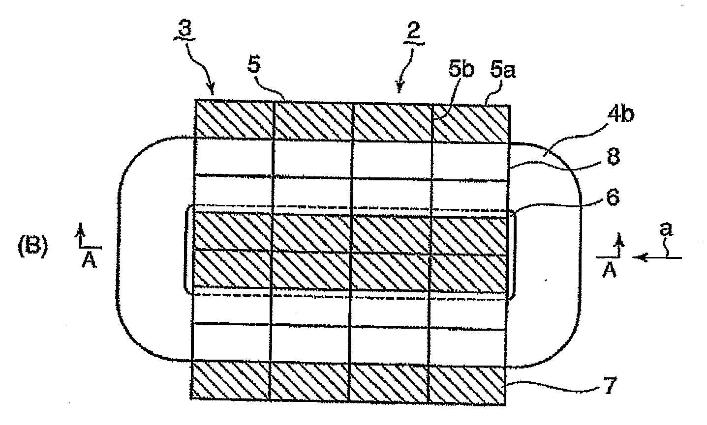
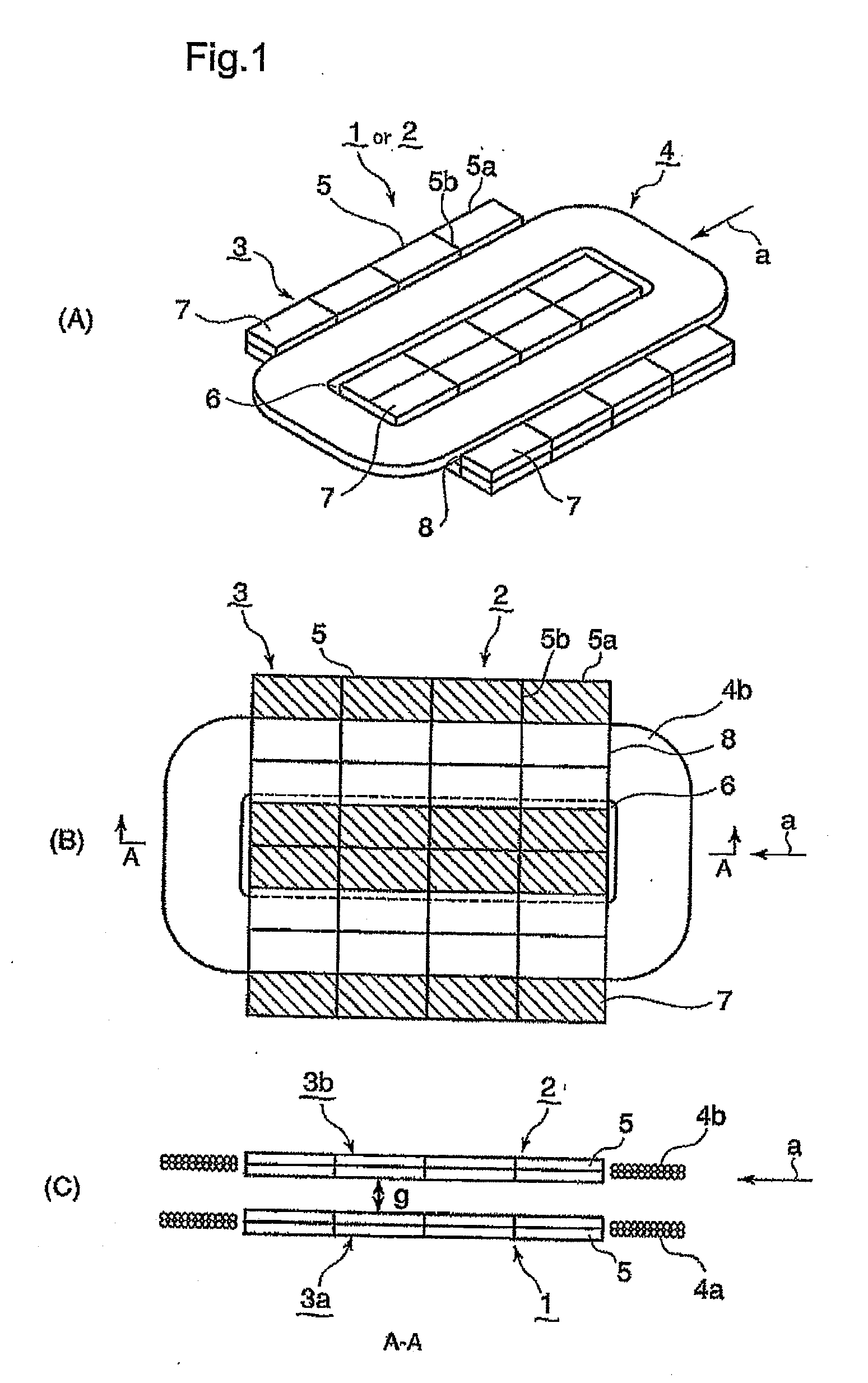
[0060]A first embodiment of the present invention will be explained with reference to FIGS. 1A to 1C in which FIG. 1A is a perspective view illustrating a power feeding portion or a power receiving portion of a noncontact type power feeder system to which the present invention is applied, FIG. 1B is a plan view illustrating the noncontact type power feeder system in which the power receiving portion and the power feeding portion are opposed face-to-face to each other, and FIG. 1C is a sectional view along line A-A in FIG. 1B. Reference to FIGS. 1A to 1C, the power feeding portion 1 or the power receiving portion 2 is composed of an E-type core 3 and the windings 4. The E-type core 3 is composed of several planar blocks 5 made of ferromagnetic ferrite, which are appropriately laid in a travel direction (a) of a mobile object and a direction orthogonal to the travel direction (a), and which are stacked one upon another while the adjacent planar blocks 5 are joined to one another by me...

Example

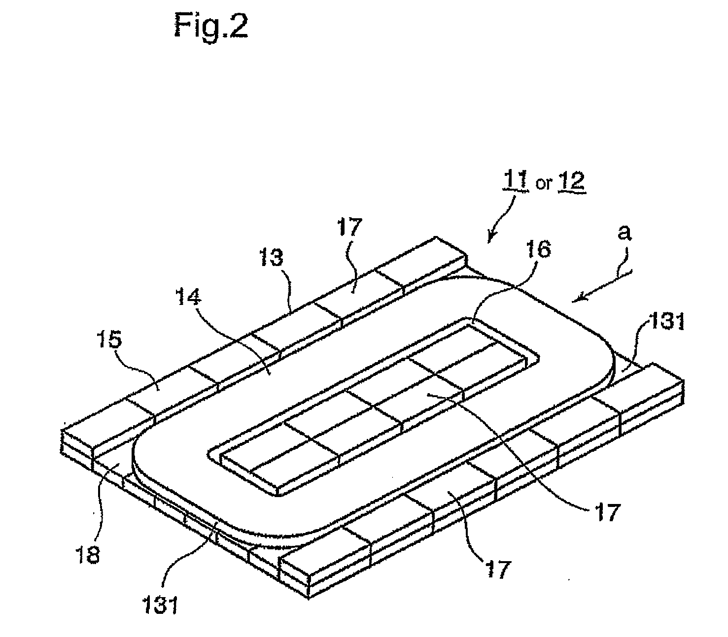
[0067]Next, explanation will be hereinbelow made of a second embodiment of the present invention with reference to FIGS. 2 to 6 in which FIG. 2 is a perspective view illustrating a power feeding portion or a power receiving portion, FIG. 3A is a plan view illustrating a noncontact type power feeder system in the second embodiment, the power feeding portion being opposed face-to-face to the power receiving portion, FIG. 3B is a sectional view along line B-B in FIG. 3A, FIG. 3C is a sectional view along line C-C in FIG. 3A, FIG. 4 is a chart showing magnetic flux lines applied to the noncontact type power feeder system, FIG. 5 is a chart showing distributions of magnetic flux density of this embodiment and the prior art system in the core widthwise direction, and FIG. 6 is a view for explaining a horizontally positional deviation of a mobile object.

[0068]Referring to FIG. 2, a power feeding portion 11 and a power receiving portion 12 in this embodiment have one and the same configurat...

Example

[0078]Explanation will be hereinbelow made of a third embodiment of the present invention with reference to FIGS. 7A to 9C. FIGS. 7A to 7C show a non contact type power feeder system in the third embodiment of the present invention, in which FIG. 7A is a plan view, FIG. 7B is a sectional view along line D-D in FIG. 7A, and FIG. 7C is a sectional view along line E-E in FIG. 7A. The embodiment shown in FIGS. 7A to 7C is different from the second embodiment so that the long sides of the primary core 23a in the power feeding portion 21 and the secondary core 23b in the power receiving portion are set to be longer toward the travel direction (a) by a length corresponding to one planer block. The shaded parts in FIG. 7A exhibit protrusions 27 in which planar blocks 25 are superposed with each other in two stages. Instead of increasing the length in the travel direction (a), each of the protrusions 27 formed inside and outside of the primary winding 24a and the secondary winding 24b has su...


PUM


Abstract

A noncontact type power feeder system for feeding a power to a mobile object, in which a power feeding portion and a power receiving portion can be easily manufactured at low costs and which can transmit a high power. The noncontact type power feeder system for a mobile object, comprises a power feeding portion provided in a surface on which the mobile object runs, and a power receiving portion provided in the lower part of the mobile object at a position facing to the power supply portion, the each of the power feeding portion and the power receiving portion is composed of windings formed in an oval shape, and a magnetic planar core formed therein with a recess in which the windings are accommodated so that the longitudinal direction of the oval shape of the windings is extended along the travel direction of the mobile object, the planer core is composed of several planar blocks each having a rectangular surface, several blocks being laid so that long sides of the rectangular surfaces are extended in the travel direction of the mobile object, in which several blocks are also laid in the direction orthogonal to the travel direction, and several blocks being superposed one upon another, the recess of the planar core is defined by thick wall parts in which the planar cores are superposed on the surface of the planar core, outside and inside of the oval shape part of the windings.

Description

BACKGROUND OF THE INVENTION[0001]1. Field of the Invention[0002]A present invention relates to a power feeder system for feeding a power to a power receiving portion provided to a mobile object such as an electric vehicle in a track way type transportation system or an electric mobile, from a power feeding portion provided in a track way, a road surface or the like on which the mobile object runs.[0003]2. Description of the Related Art[0004]A noncontact type power feeder system is adapted to feed a power in a noncontact manner from a power feeding portion to a power receiving portion which are opposed face-to-face to each other through a gap therebetween, with the use of electromagnetic induction. The power feeding portion and the power receiving portion are provided therein with cores made of magnetic material such as ferrite. An E-shape core as an example thereof, has a plurality of protrusions and a plurality of recesses which are defined between the adjacent protrusions, and win...

Claims


Application Information

Patent Timeline
IPC IPC(8): H02J7/00B60M7/00H01F38/14
CPCB60L5/005B60M7/00B60L2200/26H02J5/005H01F38/14Y02T10/7072Y02T90/14B60L53/126Y02T10/70H02J50/70H02J50/10H02J50/005Y02T90/12
Inventor MORITA, KATSUAKIMITAKE, MASAYAYAMAGUCHI, MASAHIROYAMADA, MASAOMIYAMASHITA, HIROSHIKATAHIRA, KOSUKE
Owner MITSUBISHI HEAVY IND ENG LTD
Why Eureka
Try Eureka