
Pulse width modulator with systematic frequency shifting and controlling method thereof

a frequency shifting and pulse width technology, applied in the direction of electric variable regulation, process and machine control, instruments, etc., can solve the problems of rfi and other forms of interference, wide switching frequency range, and high output ripple which is detrimental, and achieve excellent output regulation, minimal interference, and high efficiency

Inactive Publication Date: 2008-06-05
ANALOG MICROELECTRONICS
View PDF2 Cites 27 Cited by
  • Summary
  • Abstract
  • Description
  • Claims
  • Application Information

AI Technical Summary

Benefits of technology

[0004]It is the object of the present invention to provide a high efficiency switching regulator over a broad current range while maintaining excellent output regulation and minimal interference.
[0005]In accordance with these objectives, circuits and methods are described which detect a narrow on-time pulse and systematically lower the switching frequency. In so doing, switching losses are reduced. The frequency is decreased in finite steps to reflect the change in load. Additionally, the frequency can be divided down to a sub-harmonic of the original frequency, so as not to interfere with another known circuit.

Problems solved by technology

Sometimes referred to as “Burst-Mode” or “Sleep-Mode”, these devices characteristically have high output ripple which is detrimental in many applications.
Unfortunately, the resulting wide range in switching frequency gives rise to RFI and, or other forms of interference.

Method used


Image

  • Pulse width modulator with systematic frequency shifting and controlling method thereof
  • Pulse width modulator with systematic frequency shifting and controlling method thereof
  • Pulse width modulator with systematic frequency shifting and controlling method thereof

Examples


Embodiment Construction

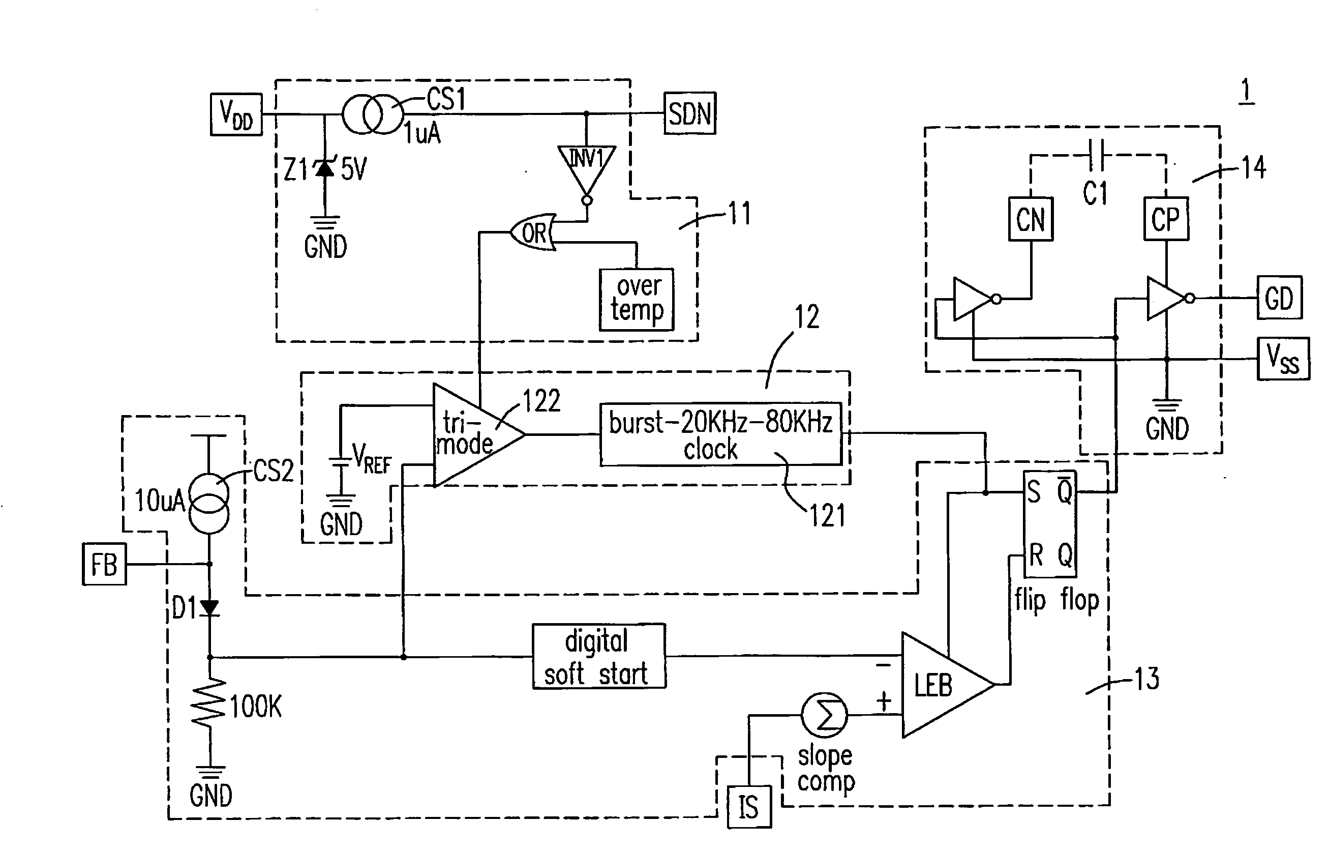
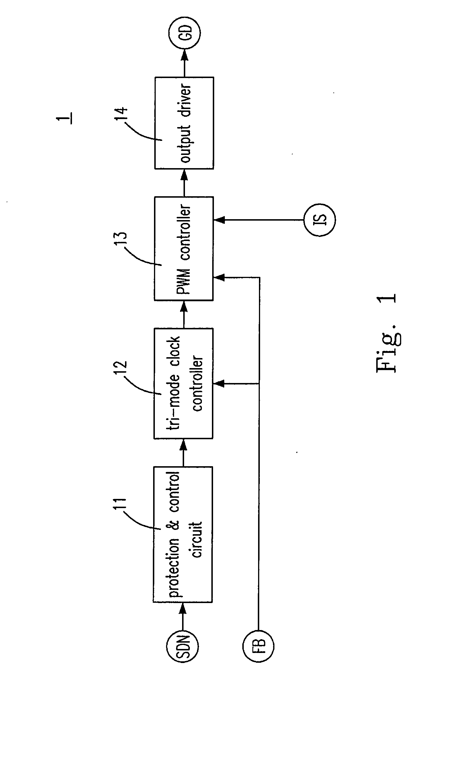
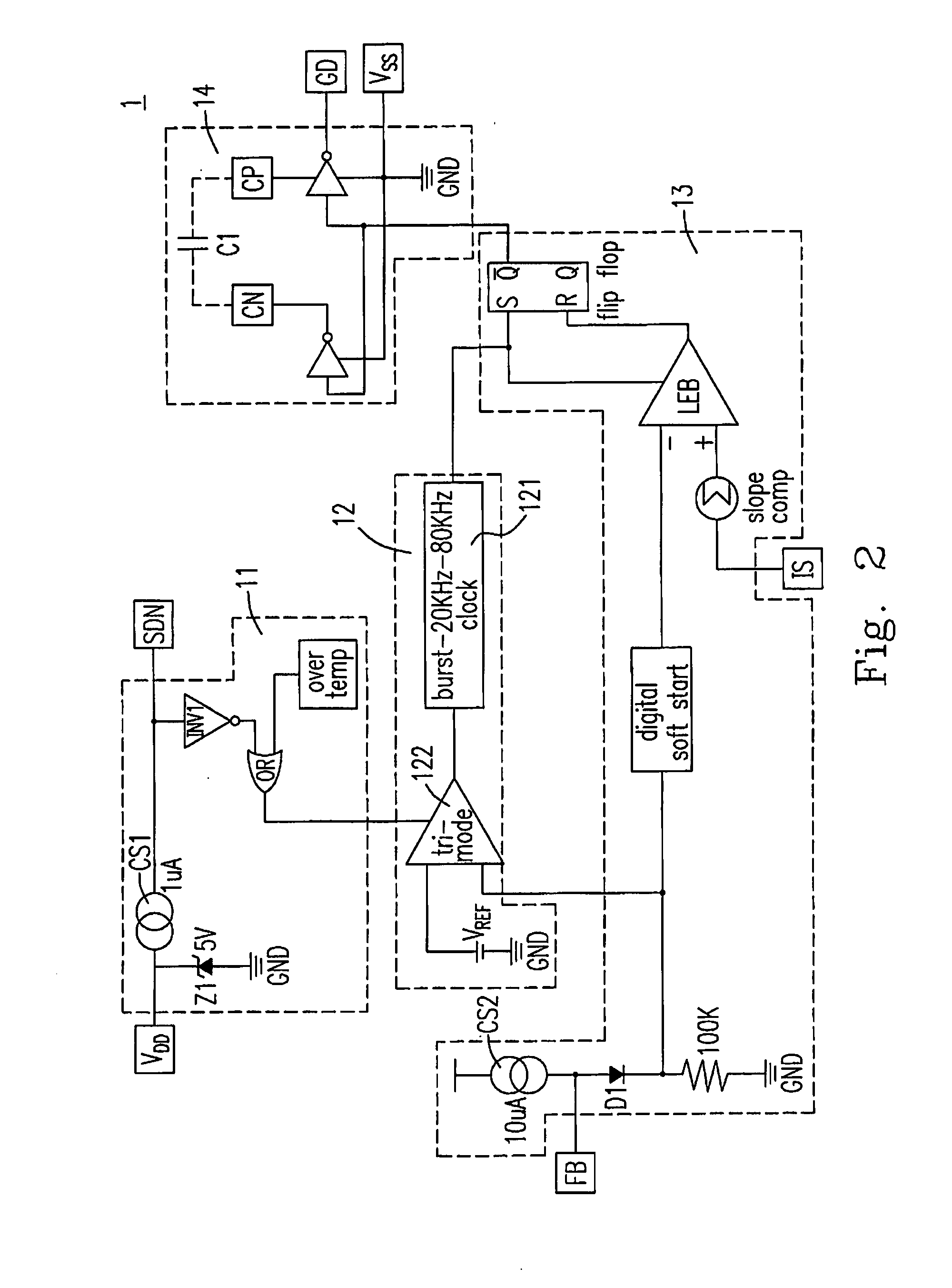
[0020]Please refer to FIG. 1, which shows a system block diagram of a switching regulator having systematic frequency shifting according to the first preferred embodiment of the present invention. In which, the proposed switching regulator 1 includes a protection and control circuit 11, a tri-mode clock controller 12, a pulse-width modulation (PWM) controller 13 and an output driver 14. The protection and control circuit 11 receives an external shutdown signal SDN input by a user to shutdown the switching regulator 1, and the protection and control circuit 11 could also shutdown the switching regulator 1 when the temperature inside the switching regulator 1 is higher than a predetermined level. The PWM controller 13 receives a feedback signal of an output voltage across an external load (not shown) via an external terminal FB and a current sense signal from a current sensor (not shown) via an external terminal IS and generates a pulse train. The output driver 14 receives the pulse t...


PUM


Abstract

The configurations of a switching regulator and the controlling methods thereof are provided. The proposed switching regulator includes a pulse-width modulation controller generating a pulse train, an output driver receiving the pulse train and generating a driving signal so as to turn an external switch on / off, and a tri-mode clock controller including a system clock generating a clock signal to control a timing of the pulse train and a tri-mode circuitry receiving a feedback signal of an output voltage across an external load and generating a control signal to control a frequency of the clock signal according to the feedback signal.

Description

FIELD OF THE INVENTION[0001]The present invention relates to a pulse width modulator (PWM). More particularly, the present invention relates to a PWM with systematic frequency shifting.BACKGROUND OF THE INVENTION[0002]Pulse width modulators have been developed which incorporate various forms of frequency control to save power under light or no-load conditions. For example, LTC U.S. Pat. No. 5,481,178 generates a control signal to disable one or more switching transistors. Sometimes referred to as “Burst-Mode” or “Sleep-Mode”, these devices characteristically have high output ripple which is detrimental in many applications. Other schemes use variable frequency control (PFM) to save power and reduce ripple. Unfortunately, the resulting wide range in switching frequency gives rise to RFI and, or other forms of interference.[0003]Keeping the drawbacks of the prior arts in mind, and employing experiments and research full-heartily and persistently, the applicant finally conceived a puls...

Claims


Application Information

Patent Timeline
Patent Type & Authority Applications(United States)
IPC IPC(8): G05F1/10G05F1/00
CPCH02M1/32Y02B70/16H02M2001/0032H02M3/156H02M1/0032Y02B70/10
Inventor ROSENTHAL, BRUCE
Owner ANALOG MICROELECTRONICS
Learn More