Coil component

a coil and component technology, applied in the direction of transformer/inductance details, printed inductances, inductances, etc., can solve the problems of difficult to obtain a common mode filter having high impedance, difficult to increase the number of attempts, etc., and achieve the effect of high electrical characteristics

a coil and component technology, applied in the direction of transformer/inductance details, printed inductances, inductances, etc., can solve the problems of difficult to obtain a common mode filter having high impedance, difficult to increase the number of attempts, etc., and achieve the effect of high electrical characteristics

US20080129439A1Active Publication Date: 2008-06-05TDK CORPARATION

Image

  • Coil component
  • Coil component
  • Coil component

Examples


Embodiment Construction

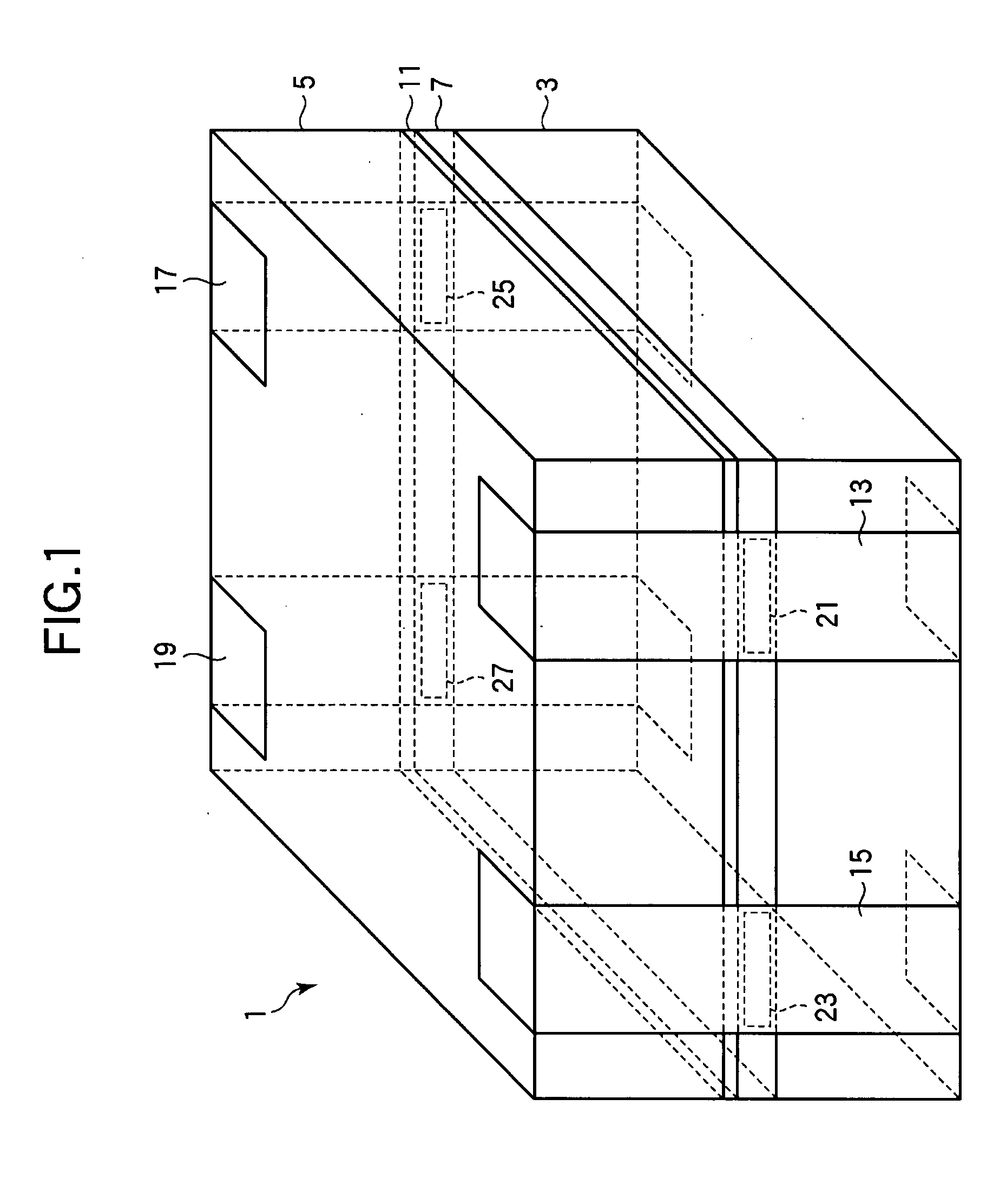
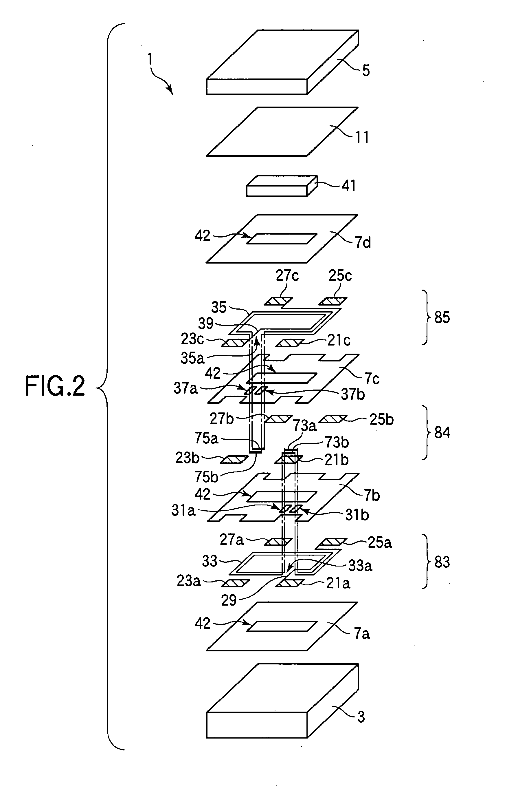
[0030]A coil component that is an embodiment of the invention will now be described with reference to FIGS. 1 to 7. A common mode filter for suppressing a common mode current which can cause electrostatic interference in a balanced transmission system will be described as an example of a coil component of the present embodiment. FIG. 1 is a perspective view of a common mode filter 1. In FIG. 1, hidden lines are indicated by broken lines.

[0031]As shown in FIG. 1, the common mode filter 1 has a rectangular parallelepiped outline which is formed by stacking thin films between two magnetic substrates 3 and 5 in the form of thin rectangular parallelepiped plates disposed to face each other. The common mode filter 1 is what is called a 1005-type surface-mount component (whose longer sides are 1.0 mm long and whose shorter sides are 0.5 mm long). An insulation layer 7 and a bonding layer 11 are formed in the order listed between the magnetic substrates 3 and 5 using thin-film forming techn...


PUM

PropertyMeasurementUnit
width w1aaaaaaaaaa
widthaaaaaaaaaa
thicknessaaaaaaaaaa

Abstract

The invention relates to surface-mount type coil components having a mounting surface for mounting them on a printed circuit board or hybrid IC (HIC) and provides a coil component having high electrical characteristics. A common mode filter includes a coil conductor formed in a spiral shape, cut ends which are parts of the coil conductor cut to face each other, and bridge conductors formed so that an insulation film is interposed between the coil conductor and the same to connect the cut ends to each other.

Description

BACKGROUND OF THE INVENTION[0001]1. Field of the Invention[0002]The present invention relates to a surface-mount type coil component having a mount surface for mounting the same on a printed circuit board or a hybrid IC (HIC).[0003]2. Description of the Related Art[0004]Known coil components mounted on circuits in electronic apparatus such as personal computers and cellular phones include wire-wound type components provided by winding a copper wire around a ferrite core, multi-layer type components provided by forming a coil conductor pattern on a surface of a magnetic sheet made of ferrite and stacking such magnetic sheets one over another, and thin-film type components provided by forming insulation films and coil conductors constituted by metal thin films alternately using thin film forming techniques. Multi-layer type and thin-film type coil components can be easily provided with a small size.[0005]Known coil components include common mode filters for suppressing a common mode c...

Claims


Application Information

Patent Timeline
05 Jun 2008
Publication
US20080129439A1
IPC
H01F5/00; H01F5/06
CPC
H01F17/0013; H01F27/323; H03H2001/0092; H01F2017/0093; H01F2017/002
Inventors
NISHIKAWA, TOMONAGA; ITO, TOMOKAZU