Electronic electric meter for networked meter reading

a networked, electric meter technology, applied in the direction of sustainable buildings, wireless architecture, instruments, etc., can solve the problems of customer complaints, difficult to cost-effectively measure electricity usage, and difficulty for service personnel to access the meter for reading, inspection and maintenance, etc., to facilitate the operation of changing circuit boards or modules

Inactive Publication Date: 2008-06-05
SILVER SPRING NETWORKS
View PDF41 Cites 46 Cited by
  • Summary
  • Abstract
  • Description
  • Claims
  • Application Information

AI Technical Summary

Benefits of technology

[0015]Yet another object of the invention is to provide an electronic electric meter that is of a modular construction to easily allow an operator to change circuit boards or modules depending upon the desired data communication network.

Problems solved by technology

However, it is often difficult for the service person to access the meter for reading, inspection and maintenance.
These estimated billings often lead to customer complaints.
This makes it difficult to cost-effectively measure electricity usage for each user to promote fair billing and encourage conservation.
Manual reading of electric meter is highly labor intensive, inefficient and very expensive.
However, most of these prior art systems have achieved little success.
The use of existing telephone lines and power lines to communicate commodity usage data to a utility have encountered significant technical difficulties.
In a telephone line system, the meter data may interfere with the subscriber's normal phone line operation, and would require cooperation between the telephone company and the utility company for shared use of the telephone lines.
A telephone line communication link would also require a hard wire connection between the meter and the main telephone line, increasing installation costs.
Another disadvantage of the PLC system is the possibility of losing data from interference on the power line.
However, such prior art systems have disadvantages.
The first disadvantage is that the device mounted to the meter generally has a small transceiver having a very low power output and thus a very short range.
Another disadvantage is that the device attached to the meter must be polled on a regular basis by the data interrogator.
The device attached to the meter is not able to initiate a communication.
The mobile and hand-held data interrogators are of limited value since it is still necessary for utility service personnel to travel around neighborhoods and businesses to remotely read the meters.
The systems utilizing a data interrogator at fixed locations still have the disadvantages of low power output from the devices attached to the meters, and requiring polling by the data interrogator to initiate communication.
Therefore, although automatic meter reading systems are known in the prior art, the currently available automatic meter reading systems suffer from several disadvantages, such as low operating range and communication reliability.

Method used


Image

  • Electronic electric meter for networked meter reading
  • Electronic electric meter for networked meter reading
  • Electronic electric meter for networked meter reading

Examples


Embodiment Construction

Electronic Electric Meter

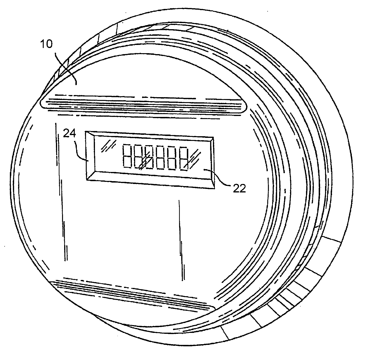
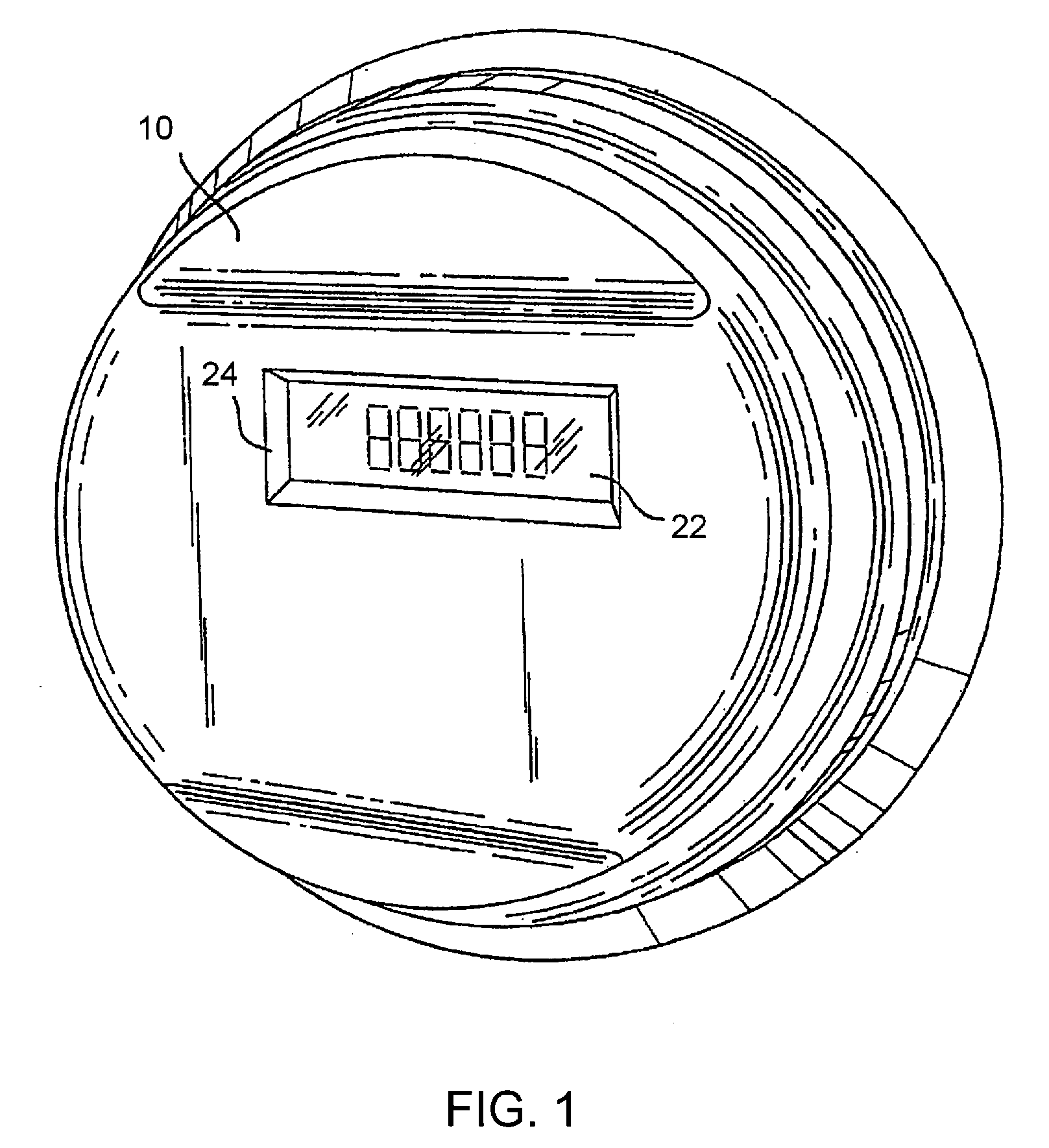
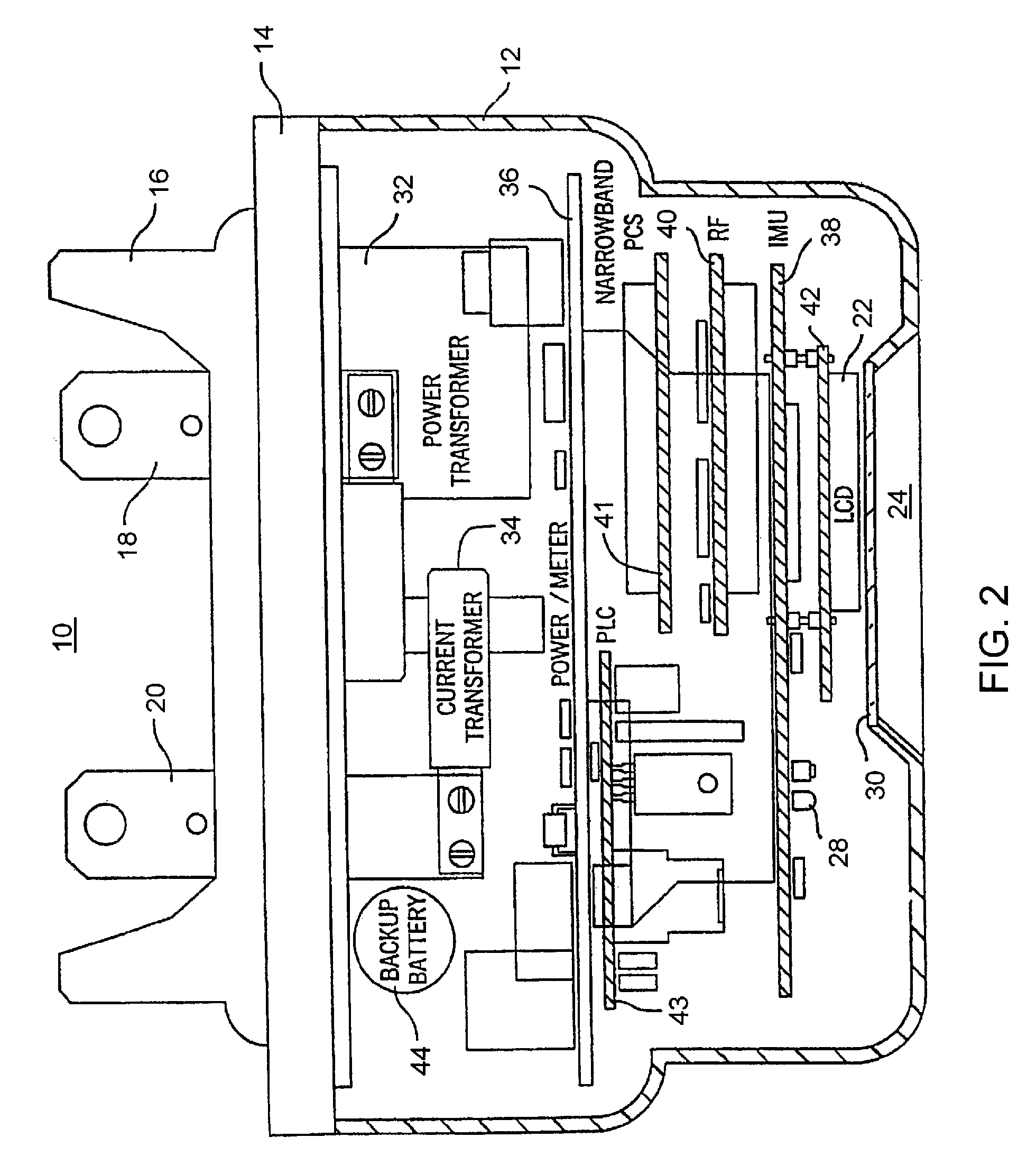
[0037]FIGS. 1 and 2 show a fully integrated, self-contained electronic electric meter 10 for measuring electricity usage and monitoring power quality. The meter 10 is operable for both single phase and three phase electric power installations. The meter 10 includes a top cover 12 attached to a meter base 14. Extending outwardly from the meter base 14 is a mounting frame 16 and a pair of terminals 18, 20. The meter 10 easily retrofits into existing meter sockets by insertion of terminals 18, 20 into the sockets and interlocking the mounting frame to secure the meter in place. The terminals 18, 20 complete the connection between the electric power line and the meter 10. The meter 10 further includes a liquid crystal display 22 for displaying meter readings and settings, units of measure and status conditions. The top cover 12 includes a rectangular opening 24 for the LCD 22. A transparent piece of glass or plastic, which fits the shape and size of the display ...


PUM


Abstract

An electronic electric meter for use in a networked automatic meter reading environment. The electric meter retrofits into existing meter sockets and is available for new meter installations for both single phase and three phase electric power connections. The electric meter utilizes a modular design which allows the interface modules to be changed depending upon the desired communication network interface. The meter measures electricity usage and monitors power quality parameters for transmission to the utility. The gateway node transmits this data to the utility over a commercially available fixed wide area network (WAN). The meter also provides direct communication to the utility over a commercially available network interface that plugs into the meter's backplane or bus system bypassing the local area network communication link and gateway node.

Description

CROSS-REFERENCE TO RELATED APPLICATION[0001]This application is a continuation-in-part of prior filed co-pending U.S. patent application Ser. No. 11 / 894,333, filed Aug. 21, 2007, which is a divisional of U.S. patent application Ser. No. 10 / 672,781, filed Sep. 26, 2003, now U.S. Pat. No. 7,277,027, issued Oct. 2, 2007, which is a continuation of U.S. patent application Ser. No. 10 / 319,856, filed Dec. 13, 2002, which is a continuation of U.S. patent application Ser. No. 09 / 242,792, filed Feb. 23, 1999, now U.S. Pat. No. 6,538,577, issued Mar. 25, 2003, the entire contents of all of which are hereby incorporated by reference.BACKGROUND OF THE INVENTION[0002]The present invention relates to apparatus for measuring usage of a commodity. More particularly, the invention relates to an electronic electric meter for measuring consumption of electricity and communicating that usage data and other power information to a utility over a two-way wireless local area network (LAN) to a remotely loc...

Claims


Application Information

Patent Timeline
Patent Type & Authority Applications(United States)
IPC IPC(8): G08C15/06
CPCG01D4/002H04Q2209/823G01D4/008H04Q9/00Y02B90/242Y04S20/322Y04S20/42Y02B90/245Y02B90/241Y02B90/246Y04S20/32Y04S20/40H04Q2209/40H04Q2209/75H04Q2209/60G01D4/004G01D2204/45Y02B90/20Y04S20/30
Inventor VASWANI, RAJFLAMMER, GEORGEDRESSELHUYS, DONN R.
Owner SILVER SPRING NETWORKS
Why Eureka
Try Eureka