Method and apparatus for creating optical images

Active Publication Date: 2008-06-05
DRAGONFISH TECH
View PDF11 Cites 56 Cited by
  • Summary
  • Abstract
  • Description
  • Claims
  • Application Information

AI Technical Summary

Benefits of technology

[0021]Similarly, applying the methods of the present invention to create a traditional LED stop-turn-tail lamp, results in a savings of approximately 50% over the most efficient products currently on the market. The optical efficiency improvement in the design of this improved LED-based product results in a more reliable product which produces less heat, has r

Problems solved by technology

However, in most instances there is a significant loss of electromagnetic energy by the time it reaches the image plane.
This type of illumination would be very useful for many industrial purposes, but in the past, has been difficult or impossible to achieve.
In past non-imaging solutions, designers used simplified surface geometry to approximate a desired output distribution resulting in non-optimal solutions whic

Method used


Image

  • Method and apparatus for creating optical images
  • Method and apparatus for creating optical images
  • Method and apparatus for creating optical images

Examples


Example

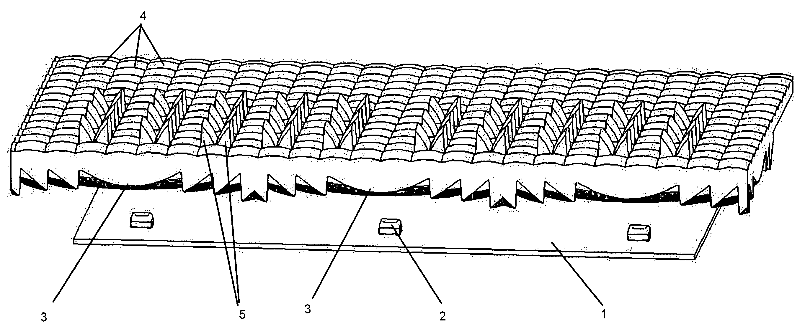
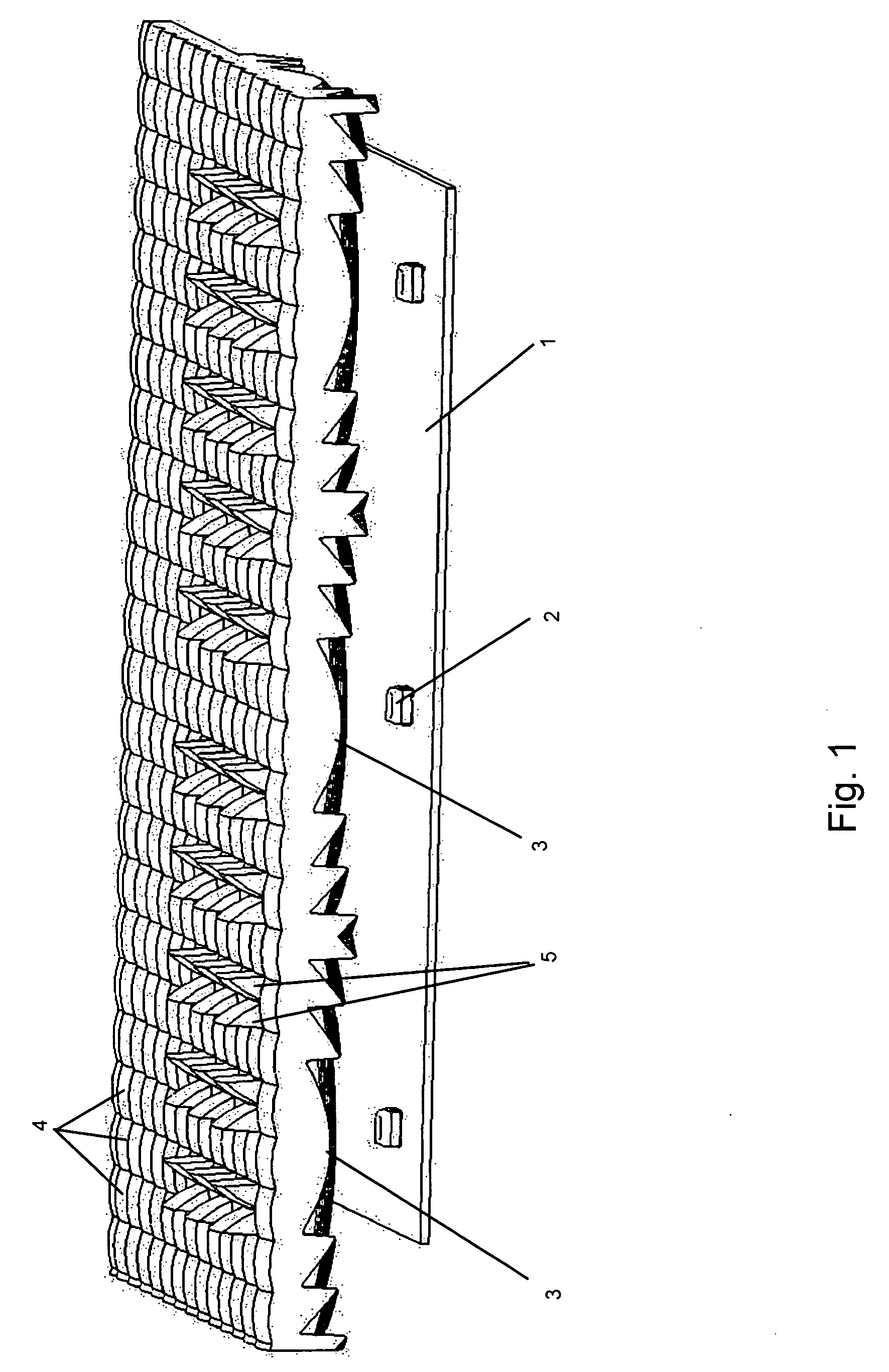
[0040]The present invention relates to an improved light shaping method and devices and lenses made therefrom. The lenses and devices made in accordance with the method of the present invention have wide ranging uses in various applications including portable lamps and specialty lighting, over-land vehicles, watercraft, aircraft and manned spacecraft, automobiles, trucks, boats, ships, buses, vans, recreational vehicles, bicycles, motorcycles, mopeds, motorized cars, electric cars, airplanes, helicopters, space stations, shuttlecraft and the like; camping lanterns, head or helmet mounted lamps as used in mining or spelunking, hand-held flashlights and the like; advertising-use lamps (such as search lamps), street lighting, traffic lights, railroad signals, emergency lighting activated during power failures and information displays.

[0041]The present invention provides an energy efficient and highly accurate method for distributing pseudo-collimated electromagnetic radiation (light) i...


PUM


Abstract

A light transforming method and device that includes a lens having one or more specifically shaped surfaces designed to generate an output image by directing the appropriate amount of electromagnetic energy from a pseudo-collimated beam to the required regions of the output image for the purpose of recreating the output image. An LED is collimated to produce the minimum spot size at the projection plane reasonably achievable and the pseudo-collimated light source impinges on the image shaping lens surface(s) such that the light is redistributed in correct proportion and angle to generate the predetermined output image. The image generating surface of the present invention is defined by a multitude of triangular facets that define a free-form surface shape such that when the energy distribution pattern exits the free-form surface the output image closely resembles the required output distribution pattern.

Description

FIELD OF THE INVENTION[0001]The present invention relates generally to the redistribution of radiant, particularly an electromagnetic energy to achieve efficient and low cost products. More particularly, it relates to an apparatus and method for the efficient distribution of light energy into a pre-determined image pattern.BACKGROUND OF THE INVENTION[0002]Optical design for the distribution of electromagnetic radiation is generally broken down into two principal fields, imaging and non-imaging optics. (In this specification, “light” and “optical” comprise portions of the electromagnetic spectrum which include the visible spectrum and which may lie outside of the visible spectrum.) The field of imaging optics can be defined as the science of transferring electromagnetic energy from an object plane to an image plane with minimal distortion. The “object plane” or “input image” can be defined as a predetermined energy input distribution, while the “image plane” or “output image” can be ...

Claims


Application Information

Patent Timeline
IPC IPC(8): F21V5/08B60Q1/44B60Q1/34
CPCB60Q1/34F21Y2101/02F21V5/08B60Q1/44F21Y2115/10
Inventor CONDON, PATRICK JEFFERYPRUSS, MARK BRYAN
Owner DRAGONFISH TECH
Why Eureka
Try Eureka