Sediment containment barrier

a technology of sediment containment and containment barrier, which is applied in the direction of dykes, hydraulic engineering, marine site engineering, etc., can solve the problems of falling out of compliance with many building ordinances and bmps, frequent costly repairs and replacements, and low durability, so as to avoid the need for retrenching, facilitate cleanup, and facilitate installation

Inactive Publication Date: 2008-06-05
WORLD TEXTILE & BAG
View PDF2 Cites 13 Cited by
  • Summary
  • Abstract
  • Description
  • Claims
  • Application Information

AI Technical Summary

Benefits of technology

[0019]An additional objective of the invention is to provide a barrier comprising an impermeable core that collects silt and sediment on the outside of the barrier, thereby keeping the barrier permeable core uncontaminated, and facilitating cleanup by only requiring the removal by shovel of sediment piled against the side of the barrier.
[0020]An additional objective of the invention is to provi...

Problems solved by technology

While effective as a dirt or silt containment barrier, the semi rigid outer shell is easily crushed by construction traffic, causing it to fall out of compliance with many building ordinances and BMPs.
When used in active production areas of a construction site, the low durability prompts frequent costly repairs and replacements to be needed.
Even before subjected to environmental and vehicular damage, the device is prone to undermining, as described above.
Thus, this product is ineffective to meet the needs of dirt and silt containment barriers around jobsites.
The wattles fail in several ways at active construction sites: 1) Even with the slightest amount of construction traffic running over the device, the inner core of polyethylene foam becomes oblong, often times causing it to fall out of compliance.
2) The outer shell is not durable enough to hold up for long periods of time without maintenance or replacement, and is prone to tear.
Breach of the outer shell can lead to the scattering of small pieces of foam over the construction site and ultimately into the very storm drains sought to be protected.
Thus, this product is similarly ineffective to meet the needs of dirt ...

Method used


Image

  • Sediment containment barrier
  • Sediment containment barrier
  • Sediment containment barrier

Examples


Embodiment Construction

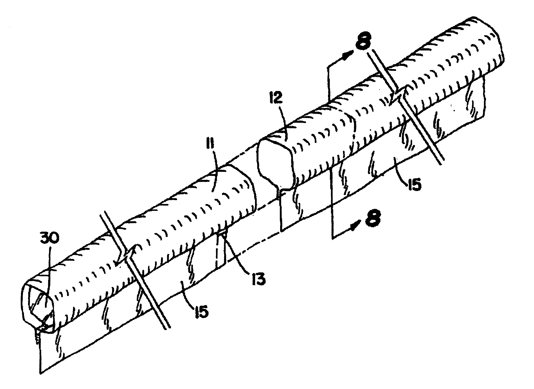
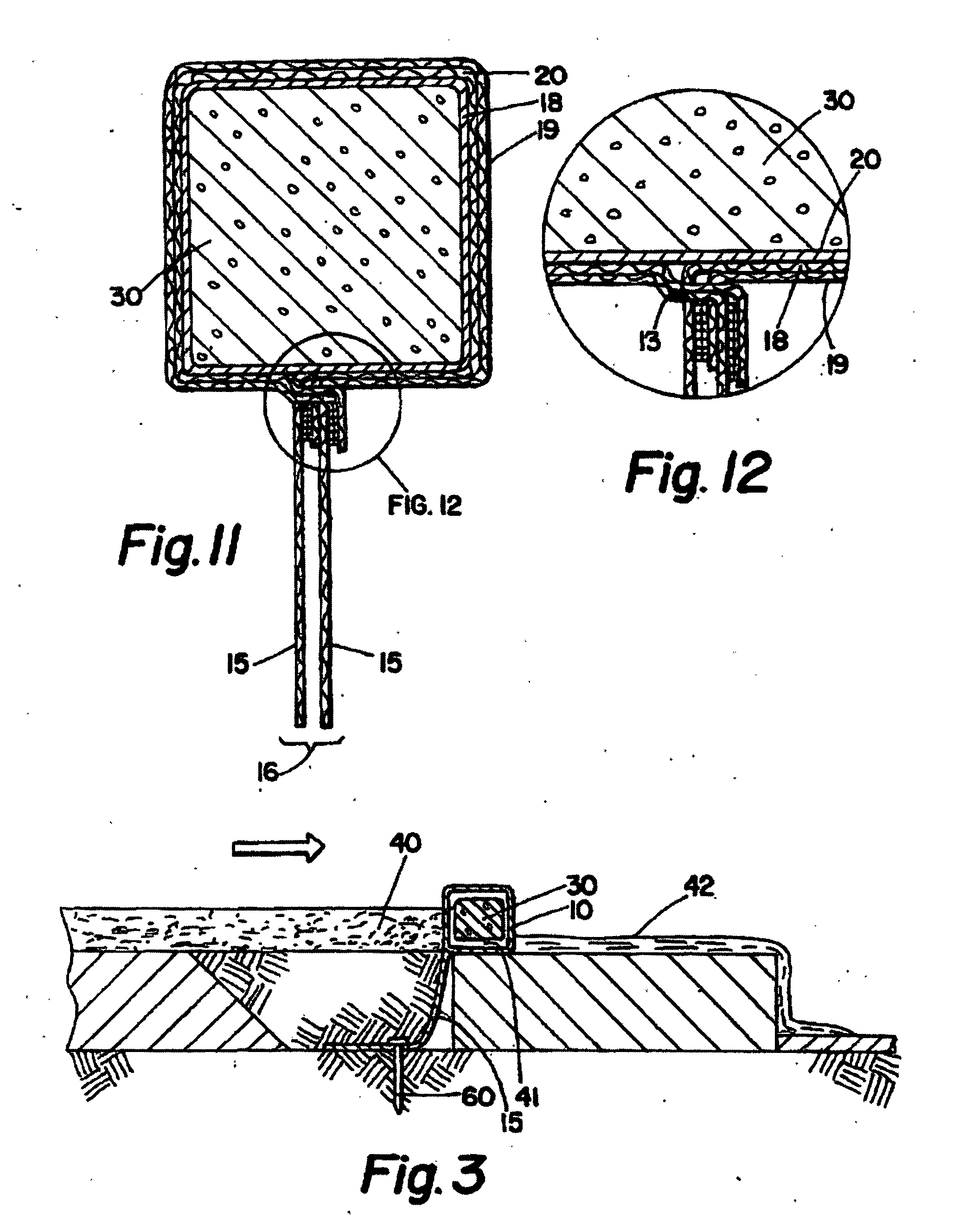
[0035]The present invention is a sediment containment barrier 1 comprising an outer shell 10 and tail 15 made from a filtering material (in a preferred embodiment a high flow monofilament woven polypropylene filter fabric), and an inner core 30 of rebounding foam (preferably polyurethane foam) sealed in a water impermeable (preferably polyethylene) middle layer 20. See FIGS. 4, 5, 7 and 10. In order to accomplish the above-stated objects of the invention, the barrier combines three layers of materials that work together to improve overall performance. Throughout this application the term sediment containment barrier may be interchanged with the common term for the device, wattle.

[0036]Outer shell 10 preferably consists of a high tensile strength (preferably 250-375 lb and less preferably 200-600 lb), high silt and sediment filtration, high water flow and high resistance to clogging, heavy duty, UV stabilized geotextile fabric that is capable of holding up to construction area abuse....


PUM


Abstract

A sediment containment barrier capable of functioning in an outdoor environment for 18-24 months or more, while offering full rebound to compression impacts even after exposure to rain, construction traffic, and other harsh elements of an active construction site. Through a protected central core of foam or air surrounded by a water impermeable middle membrane and outer filtering shell, the barrier is able to withstand being run over by construction traffic hundreds of times while rebounding to its original shape and more importantly maintaining its compliance as an effective dirt and silt containment barrier. Due to the filtering qualities and the embedded nature of the barrier, the barrier offers high flow, reduction in the ponding of water, the effective filtration of sediment and silt, and a lower height than conventional sediment containment barriers.

Description

RELATED APPLICATION[0001]This application claims priority from U.S. provisional application with Ser. No. 60 / 872,371, which was filed on 30 Nov. 2006. The disclosure of this provisional application is incorporated by reference herein as if set out in full.FIELD OF THE INVENTION[0002]The present invention relates to construction job sites and large scale commercial developments, particularly with regard to the containment of dirt, sediment and silt runoff at such locations.GENERAL BACKGROUND[0003]Erosion control is an issue societies have faced for centuries. Over the years various means have been used to adequately regulate erosion, and the related regulation of silt and runoff. One device commonly in use to achieve this is the wattle. A wattle is a fabrication of poles interwoven with slender branches, withes or reeds. They are typically laid continuously along a slope to intercept surface water runoff and create a “ponding” effect. This reduces the runoff water velocity allowing a...

Claims


Application Information

Patent Timeline
IPC IPC(8): E02D17/13
CPCE02B8/02E02B3/10
Inventor QUINLEY, RICHARD EVANCOLE, CECIL PERSHING
Owner WORLD TEXTILE & BAG
Why Eureka
Try Eureka