Fuel cells

Inactive Publication Date: 2008-06-05
TOYOTA JIDOSHA KK
View PDF2 Cites 22 Cited by
  • Summary
  • Abstract
  • Description
  • Claims
  • Application Information

AI Technical Summary

Benefits of technology

[0004]There would thus be a demand for improving the water dis

Problems solved by technology

This porous structure with the hydrophobic pores and the hydrophilic pores for ensuring the gas flow passage and the liquid water passage, however, has limitation of the water discharge efficiency.
The water discharge efficiency may not be sufficient according to the operation state of the fuel cell.
For example, with a decrease in internal temperature of the fu

Method used


Image

  • Fuel cells
  • Fuel cells
  • Fuel cells

Examples


second embodiment

C. Second Embodiment

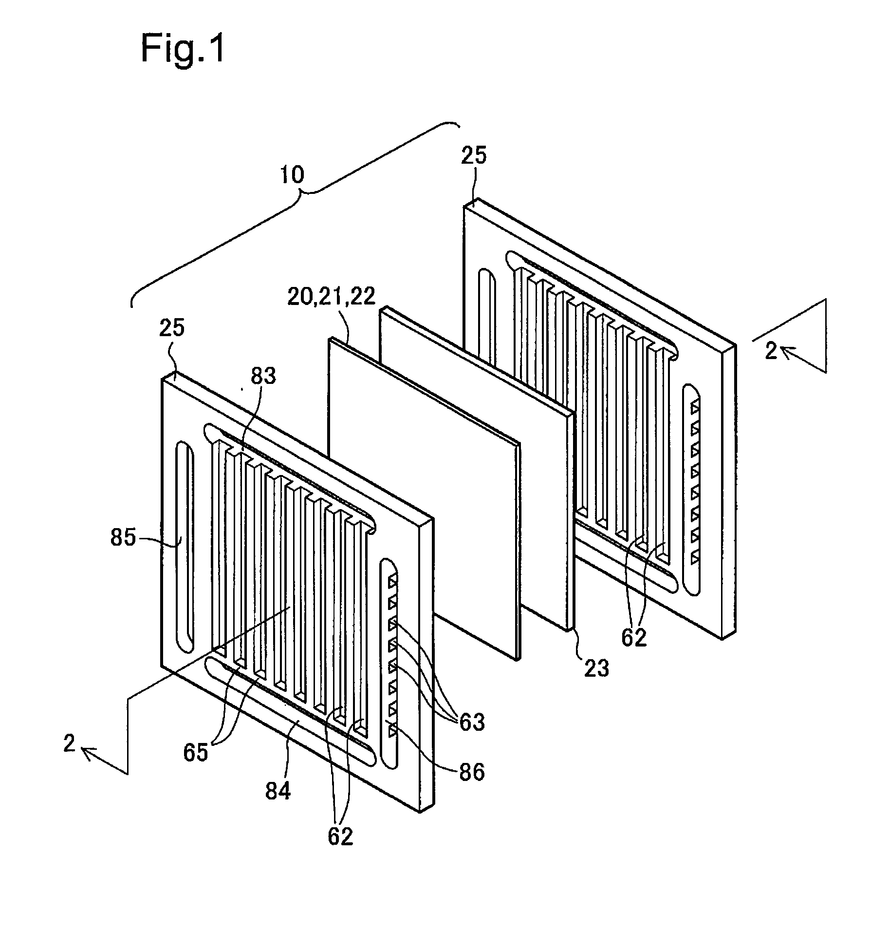
[0087]In the unit cell structure of the first embodiment, the flow path-forming porous layer 23 has a flat plane, while the surface of the gas separator 25 is designed to have the grooves 62 for formation of the inner-unit cell oxidizing gas flow path. This unit cell structure is, however, not restrictive but may be modified. FIG. 6 is a decomposed perspective view illustrating the structure of a fuel cell in a second embodiment having the reverse concave-convex relation between a gas separator and a flow path-forming porous layer. The fuel cell of the second embodiment has a gas separator 225 and a flow path-forming porous layer 223, in place of the gas separator 25 and the flow path-forming porous layer 23. The like elements in the fuel cell of the second embodiment shown in FIG. 6 to those in the fuel cell of the first embodiment shown in FIG. 1 are expressed by the like numerals and are not specifically described here.

[0088]The gas separator 225 has a substan...

third embodiment

D. Third Embodiment

[0091]In the fuel cell structures of the first embodiment and the second embodiment, the flow of the oxidizing gas wholly goes into the flow path-forming porous layer at the end of the inner-unit cell oxidizing gas flow path. This arrangement is, however, not essential, but another arrangement may be adopted instead. FIG. 8 is a sectional view showing the schematic structure of a fuel cell in a third embodiment. The illustrated area of FIG. 8 corresponds to the structure of the first embodiment shown in FIG. 3. The fuel cell of the third embodiment has a similar structure to that of the fuel cell of the first embodiment, except a gas separator 325 in place of the gas separator 25. The like elements in the fuel cell of the third embodiment shown in FIG. 8 to those in the fuel cell of the first embodiment shown in FIG. 1 are expressed by the like numerals and are not specifically described here.

[0092]The gas separator 325 included in the fuel cell of the third embod...

fourth embodiment

E. Fourth Embodiment

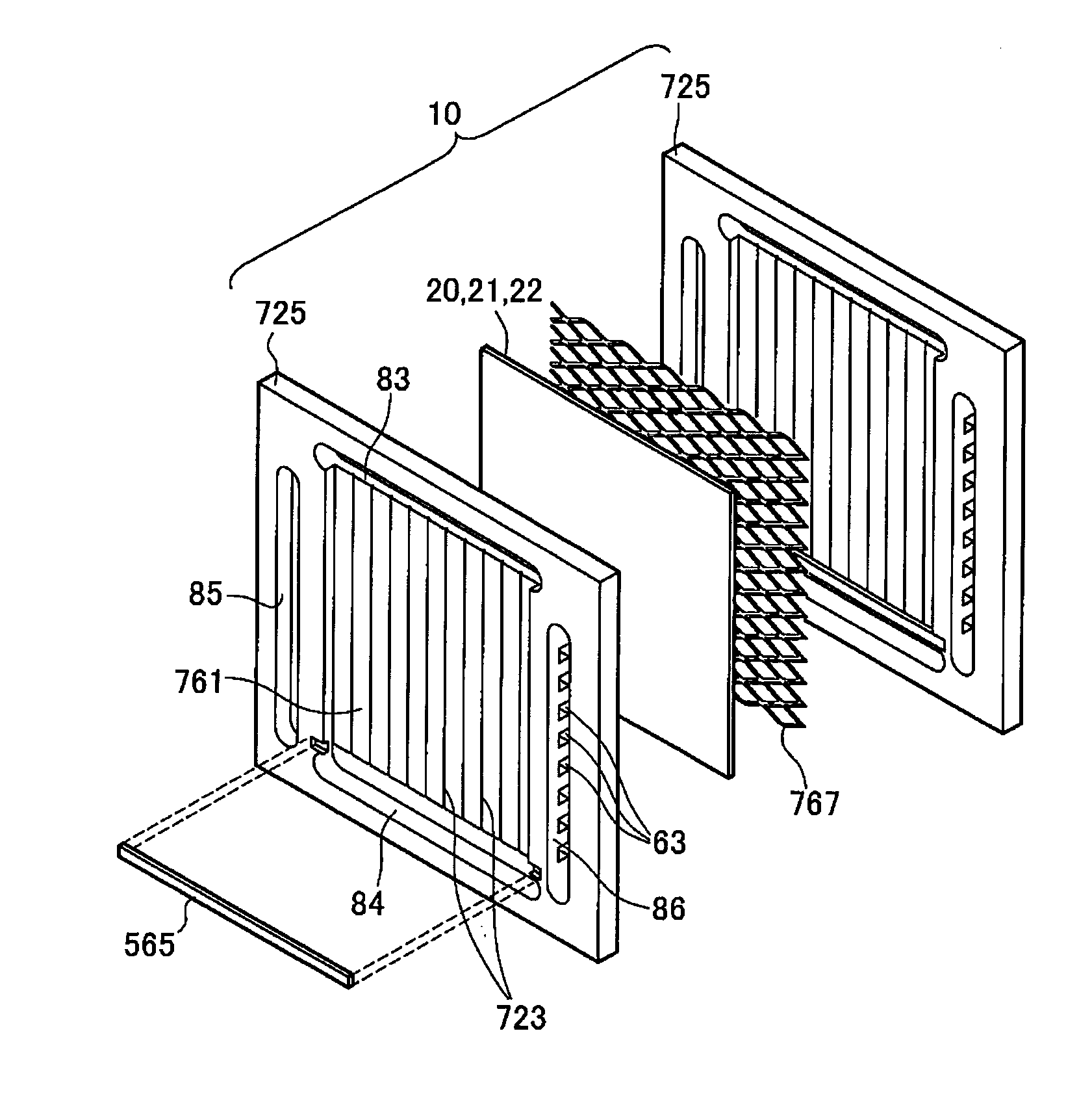
[0097]In the fuel cell structures of the first through the third embodiments, the flow path-forming porous layer 23 is located on the gas diffusion layer 22. This structure is, however, not essential, but a different structure may be adopted for the same purpose. In the different fuel cell structure, a first water guide element for continuously guiding the water produced on the electrode in the plane direction of the electrode may be located to be not in plane contact with the electrode but to be separate from the electrode. FIG. 10 is a decomposed perspective view schematically illustrating the structure of a fuel cell in a fourth embodiment. The fuel cell of the fourth embodiment has a gas separator 525 and a water guide porous layer 523, in place of the gas separator 25 and the flow path-forming porous layer 23. FIG. 11 shows the end of an inner unit-cell oxidizing gas flow path in the fuel cell of the fourth embodiment. The illustrated area of FIG. 11 corresp...


PUM


Abstract

In a fuel cell structure having an assembly of an electrolyte layer and an electrode formed on the electrolyte layer, a gas separator 25 is laminated on the electrolyte layer and the electrode and forms, in combination with the electrode, a gas flow path to make a flow of a reactive gas that is subjected to an electrochemical reaction. A first water guide element is provided between the electrode and the gas separator 25 and is arranged to enable migration of water from and to the electrode and to continuously guide water in an electrode plane direction. A gas outlet 68 is open at one end of the gas flow path to be at least partly overlapped with one end of the first water guide element and discharges the flow of the reactive gas from the gas flow path. The gas outlet 68 is designed to have a higher flow resistance of the reactive gas than a flow resistance in the gas flow path. This arrangement effectively improves the water discharge efficiency from the gas flow path formed in the fuel cell structure.

Description

FIELD OF THE TECHNOLOGY[0001]The present invention relates to fuel cells.DESCRIPTION OF THE RELATED ART[0002]In the progress of an electrochemical reaction in a fuel cell, water is produced on one electrode. Especially in polymer electrolyte fuel cells, a gas supplied to the fuel cell may be humidified since an electrolyte membrane is to be kept in the wet state. In this structure, the water content in the gas may be condensed in a gas flow path. In the fuel cell structure having the possibility of condensation of water in the gas flow path, smooth passage of the gas supplied to and discharged from the electrode and discharge passage of liquid water produced on the electrode are demanded to prevent deterioration of the cell performance due to the interference of liquid water with the supply and discharge of the gas to and from the electrode. One proposed structure for ensuring the gas flow passage and the water discharge passage provides a porous support layer that is located close ...

Claims


Application Information

Patent Timeline
IPC IPC(8): H01M8/04
CPCH01M8/04164Y02E60/50H01M2008/1095H01M8/04171
Inventor IKEDA, KOTAROANDO, MASAKI
Owner TOYOTA JIDOSHA KK
Why Eureka
Try Eureka