Image rejection calibration system

a wireless receiver and image rejection technology, applied in the direction of radio transmission, electrical equipment, transmission, etc., can solve the problems of large use of integrated low-power radio designs, and high cost of power and complexity, so as to achieve the effect of increasing image rejection

Active Publication Date: 2008-06-05
ANALOG DEVICES INC
View PDF15 Cites 33 Cited by
  • Summary
  • Abstract
  • Description
  • Claims
  • Application Information

AI Technical Summary

Benefits of technology

[0009]It is therefore an object of this invention to provide an improved method and system for increasing image rejection.

Problems solved by technology

Achieving good Image Rejection (IR) performance in heterodyne receivers is one of the most important challenges in high performance radio design and the choice of radio architecture used in many applications is very often dictated by the image rejection requirements of the overall system.
However, this comes at a cost of more expensive and power hungry filters for the first IF stage.
In general, superheterodyne receivers can be designed to have excellent selectivity and can exhibit very good image rejection performance, but this comes at a cost of power and complexity and they are not widely used in integrated low power radio designs.
However, the zero-IF architecture is prone to low frequency impairments such as 1 / f noise and DC offset problems and is not suitable for narrowband wireless communication applications such as the Flex / ReFlex pager standards and PMR radio standards such as APC025 and TETRA, where occupied spectral bandwidths of 6.25 kHz, 12 kHz and 25 kHz are required.
However, these architectures suffer from poor to moderate image rejection due to quadrature gain and phase mismatch errors in the local oscillator (LO) and signal paths.
Fundamentally, these methods rely on complex signal cancellation techniques to remove the image component.
However, due to manufacturing process tolerances, it is difficult to ensure quadrature gain and phase errors of better than 1-2% and 1-3 degrees respectively, which results in a typical image rejection performance of 25-30 dB.

Method used


Image

  • Image rejection calibration system
  • Image rejection calibration system
  • Image rejection calibration system

Examples


Embodiment Construction

[0041]Aside from the preferred embodiment or embodiments disclosed below, this invention is capable of other embodiments and of being practiced or being carried out in various ways. Thus, it is to be understood that the invention is not limited in its application to the details of construction and the arrangements of components set forth in the following description or illustrated in the drawings. If only one embodiment is described herein, the claims hereof are not to be limited to that embodiment. Moreover, the claims hereof are not to be read restrictively unless there is clear and convincing evidence manifesting a certain exclusion, restriction, or disclaimer.

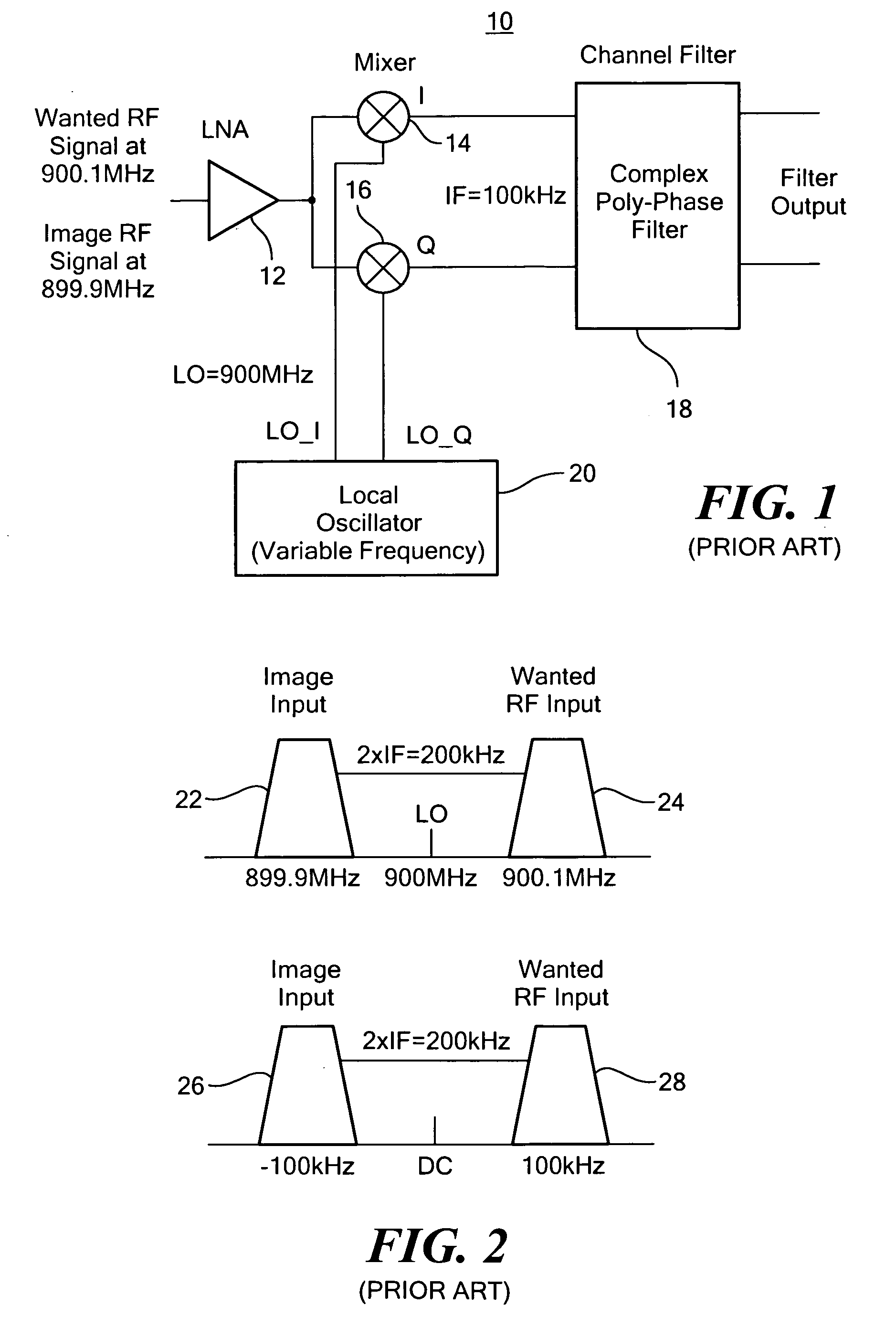
[0042]The calibration system and method of this invention is applicable for a wide range of wireless receiver architecture, e.g. heterodyne mixing circuits in radio receivers. One example of a typical receiver with which this invention may be used is a prior art low IF receiver 10, FIG. 1, which includes an input, low noise...


PUM


Abstract

Image rejection calibration includes initializing the calibration mode by applying to quadrature mixers, in place of the wanted RF input, an RF source in the frequency range of the wanted RF input, sensing the power output from the poly-phase filter, developing gain adjust and phase adjust correction values in response to the power output and adjusting in accordance with the correction values the gain of the quadrature signals from the quadrature mixers to the poly-phase filter and the phase of local oscillator quadrature signals from the local oscillator to the quadrature mixers to reduce the power output.

Description

RELATED APPLICATIONS[0001]This application claims benefit of and priority to U.S. Provisional Application Ser. No. 60 / 833,211 filed Jul. 25, 2006 and U.S. Provisional Application Ser. No. 60 / 844,255 filed Sep. 13, 2006 both incorporated herein by this reference.FIELD OF THE INVENTION[0002]This invention relates to an image rejection calibration system and method for a wireless receiver.BACKGROUND OF THE INVENTION[0003]Achieving good Image Rejection (IR) performance in heterodyne receivers is one of the most important challenges in high performance radio design and the choice of radio architecture used in many applications is very often dictated by the image rejection requirements of the overall system.[0004]For example, in a double superheterodyne architecture, careful consideration must be given to proper frequency planning to achieve good IR performance. In this architecture, the use of a high first IF frequency relaxes the constraints on the RF band select filter at the low noise...

Claims


Application Information

Patent Timeline
Patent Type & Authority Applications(United States)
IPC IPC(8): H04B1/10
CPCH04B1/28H03D7/18
Inventor QUINLAN, PHILIPCHANCA, MIGUELSHANAN, HYMANFOLEY, VINCENT
Owner ANALOG DEVICES INC
Why Eureka
Try Eureka