Resonance tuning module for implantable devices and leads

a technology of resonance tuning and implantable devices, which is applied in the field of medical devices, can solve the problems of poor functionality of the pacemaker, the inability of the implanted device to be fully functional, and the inability to achieve the desired effect of the pacemaker,

Inactive Publication Date: 2008-06-05
MEDTRONIC INC
View PDF8 Cites 74 Cited by
  • Summary
  • Abstract
  • Description
  • Claims
  • Application Information

AI Technical Summary

Problems solved by technology

The use of the magnetic-resonance imaging process with patients who have implanted medical assist devices; such as cardiac assist devices or implanted insulin pumps; often presents problems.
Since the sensing systems and conductive elements of these implantable devices are responsive to changes in local electromagnetic fields, the implanted devices are vulnerable to external sources of severe electromagnetic noise, and in particular, to electromagnetic fields emitted during the magnetic resonance imaging procedure.
A common implantable pacemaker can, under some circumstances, be susceptible to electrical interference such that the desired functionality of the pacemaker is impaired.
Such electrical interference can damage the circuitry of the cardiac assist systems or cause interference in the proper operation or functionality of the cardiac assist systems.
For example, damage may occur due to high voltages or excessive currents introduced into the cardiac assist system.
Therefore, it is required that such voltages and currents be limited at the input of such cardiac assist systems, e.g., at the interface.
However, such protection, provided by zener diodes and capacitors placed at the input of the medical device, increases the congestion of the medical device circuits, at least one zener diode and one capacitor per input / output connection or interface.
This is contrary to the desire for increased miniaturization of implantable medical devices.
Further, when such protection is provided, interconnect wire length for connecting such protection circuitry and pins of the interfaces to the medical device circuitry that performs desired functions for the medical device tends to be undesirably long.
The excessive wire length may lead to signal loss and undesirable inductive effects.
Additionally, the radio-frequency energy that is inductively coupled into the wire causes intense heating along the length of the wire, and at the electrodes that are attached to the heart wall.
A further result of this ablation and scarring is that the sensitive node that the electrode is intended to pace with low voltage signals becomes desensitized, so that pacing the patient's heart becomes less reliable, and in some cases fails altogether.
Although, conventional medical devices provide some means for protection against electromagnetic interference, these conventional devices require much circuitry and fail to provide fail-safe protection against radiation produced by magnetic-resonance imaging procedures.
Moreover, the conventional devices fail to address the possible damage that can be done at the tissue interface due to radio-frequency induced heating, and the conventional devices fail to address the unwanted heart stimulation that may result from radio-frequency induced electrical currents.

Method used


Image

  • Resonance tuning module for implantable devices and leads
  • Resonance tuning module for implantable devices and leads
  • Resonance tuning module for implantable devices and leads

Examples


Embodiment Construction

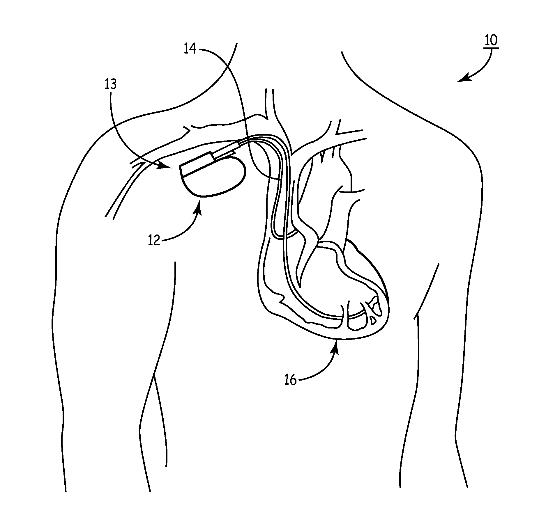
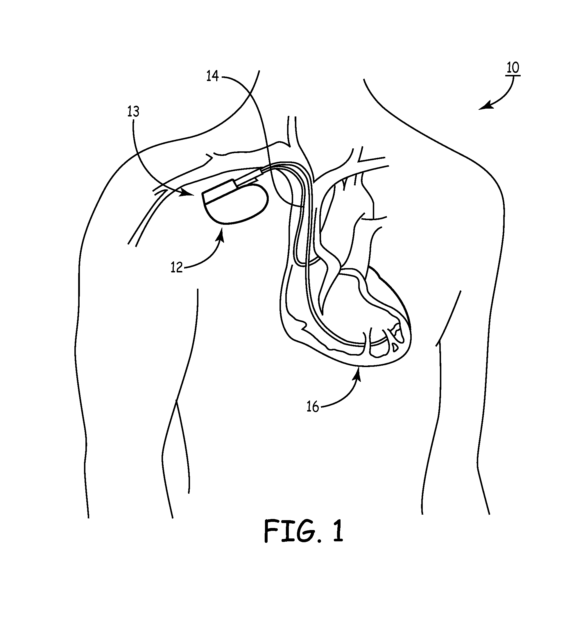
[0081]As noted above, a medical device includes an anti-antenna device to prevent or significantly reduce damaging heat, created by currents or voltages induced by outside electromagnetic energy (namely magnetic-resonance imaging), to a tissue area.

[0082]More specifically, the present invention is directed to a medical device that includes anti-antenna device, which significantly reduces the induced current on the “signal” wire of a pacing lead when the pacing lead is subjected to the excitation signal's frequency of a magnetic-resonance imaging scanner without significantly altering a low frequency pacing signal. The low frequency pacing signal may be generated by an implantable pulse generator or other pulse generator source outside the body.

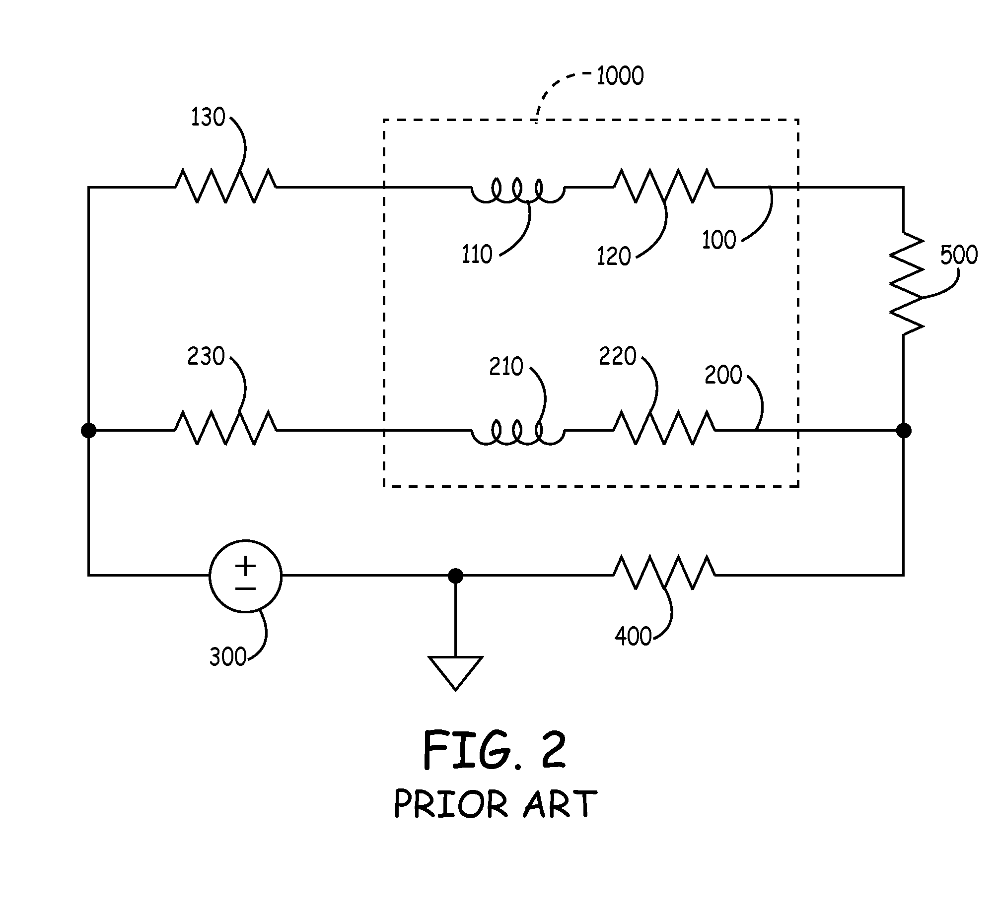
[0083]To provide an anti-antenna device, in one embodiment of the present invention utilizes a resonant circuit or circuits in line with a lead. The lead may be a signal wire of the pacing lead. Although the following descriptions of the vario...


PUM


Abstract

An implantable medical assist device includes a medical device. The medical device has a housing and electronics contained therein. A lead provides an electrical path to or from the electronics within the medical device. A resonance tuning module is located in the housing and is connected to the lead. The resonance tuning module includes a control circuit for determining a resonant frequency of the implantable medical assist device and an adjustable impedance circuit to change the combined resonant frequency of the medical device and lead.

Description

[0001]The present application is a continuation application of U.S. patent application Ser. No. 11 / 696,857, filed Apr. 5, 2007, which claims priority, under 35 U.S.C. §119(e), from U.S. Provisional Patent Application Ser. No. 60 / 744,468, filed on Apr. 7, 2006. Also, the present application claims priority, under 35 U.S.C. §119(e), from U.S. Provisional Patent Application Ser. No. 60 / 806,115, filed on Jun. 29, 2006. Furthermore, the present application claims priority, under 35 U.S.C. §119(e), from U.S. Provisional Patent Application Ser. No. 60 / 744,464, filed on Apr. 7, 2006. The present application claims priority, under 35 U.S.C. §119(e), from U.S. Provisional Patent Application Ser. No. 60 / 747,027, filed on May 11, 2006.[0002]The entire contents of U.S. Pat. No. 6,829,509 and U.S. Pat. No. 6,949,929 are hereby incorporated by reference. The entire contents of U.S. patent application Ser. No. 11 / 214,640; U.S. patent application Ser. No. 10 / 972,275; U.S. patent application Ser. No....

Claims


Application Information

Patent Timeline
Patent Type & Authority Applications(United States)
IPC IPC(8): A61N1/05
CPCA61N1/37A61N1/3718A61N1/08A61N1/05A61N2001/086A61N1/086A61N1/025A61N1/37211A61N1/37223A61N1/375A61N1/3758
Inventor GRAY, ROBERT W.MACDONALD, STUART G.
Owner MEDTRONIC INC
Why Eureka
Try Eureka