Efficiency optimized hybrid operation strategy

a hybrid operation and efficiency optimization technology, applied in position/direction control, special data processing applications, dc source parallel operation, etc., can solve the problems of low efficiency of hybrid operation strategy, low efficiency of fuel cell system for vehicle, and relatively high manufacturing cost of meas, etc., to achieve the effect of increasing system efficiency

Active Publication Date: 2008-06-05
GM GLOBAL TECH OPERATIONS LLC
View PDF35 Cites 31 Cited by
  • Summary
  • Abstract
  • Description
  • Claims
  • Application Information

AI Technical Summary

Benefits of technology

[0012]In accordance with the teachings of the present invention, a propulsion system for a fuel cell hybrid vehicle is disclosed that includes a fuel cell system (FCS) and an electric energy storage system (EESS), where the propulsion system employs an algorithm for increasing system efficiency. A power limit value is defined considering the maximum FCS efficiency and the efficiency of the EESS. If the vehicle operator requests a power greater than the power limit value, then the fuel cell system will provide the power, and if the power request from the vehicle operator is less than the power limit value, then the EESS will provide the power. The algorithm also considers changing operation conditions and parameters that impact the fuel cell system efficiency and the electric energy storage system efficiency, such as the state of charge of the EESS and regenerative braking.

Problems solved by technology

MEAs are relatively expensive to manufacture and require certain conditions for effective operation.
The dynamic power of a fuel cell system for a vehicle is limited.
Further, the time delay from system start-up to driveability and low acceleration of the vehicle may not be acceptable.
The voltage cycles can decrease the stack durability.
However, vehicle acceleration may require 100 kW or more of power.
The size of the EESS is an important design consideration for the vehicle propulsion system, which is influenced and limited by cost, weight and performance requirements.
If the SOC of the EESS does not allow for the discharge, the hybrid power system is only able to provide the maximum power from the fuel cell system.

Method used


Image

  • Efficiency optimized hybrid operation strategy
  • Efficiency optimized hybrid operation strategy
  • Efficiency optimized hybrid operation strategy

Examples


Embodiment Construction

[0018]The following discussion of the embodiments of the invention directed to an algorithm for optimizing the efficiency of a fuel cell hybrid vehicle is merely exemplary in nature, and is in no way intended to limit the invention or its applications or uses.

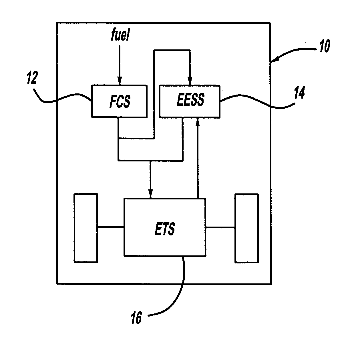
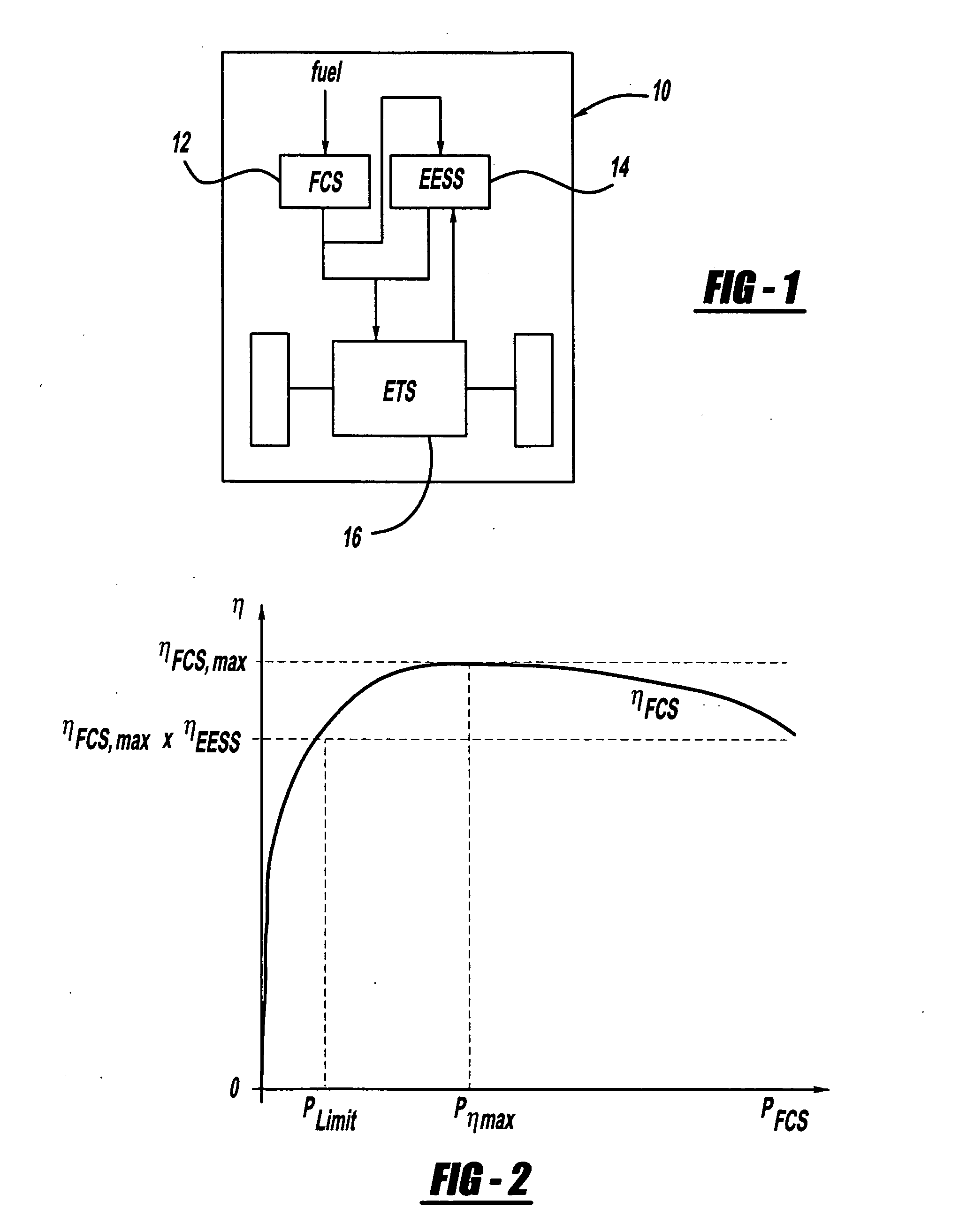
[0019]FIG. 1 is a block diagram of a fuel cell hybrid propulsion system 10 including a fuel cell system (FCS) 12, an EESS 14, and an ETS 16. The EESS 14 can be any suitable device, such as a battery, an accumulator, a super-capacitor and combinations thereof. Further required power electronic components are not shown to reduce the description to the necessary elements. As will be discussed in detail below, the present invention proposes an algorithm for providing efficient operation of a fuel cell system by determining when the requested power from the ETS 16 will be provided by the fuel cell system 12, when the requested power from the ETS 16 will be provided by the EESS 14, when the requested power from the ETS 16 will be pro...


PUM


Abstract

A propulsion system for a fuel cell hybrid vehicle that includes a fuel cell system and an EESS, where the propulsion system employs an algorithm for increasing system efficiency. A power limit value is defined as the maximum system efficiency times the charge/discharge efficiency of the EESS. If the vehicle operator requests a power greater than the power limit value, then the fuel cell system will preferably provide the power, and if the power request from the vehicle operator is less than the power limit value, then the EESS will preferably provide the power. The algorithm also considers changing operation conditions and parameters that impact the fuel cell system efficiency and the electric energy storage system efficiency, such as the state of charge of the EESS and regenerative braking.

Description

BACKGROUND OF THE INVENTION[0001]1. Field of the Invention[0002]This invention relates generally to a fuel cell hybrid vehicle with a propulsion system that employs an algorithm for efficiently determining a distributed power draw from a fuel cell system (FCS) and an electric energy storage system (EESS) and, more particularly, to a fuel cell hybrid vehicle that employs an algorithm for efficiently determining the distributed power draw from an FCS and an EESS by defining a power limit value and using EESS power if a power request is below the power limit value and using fuel cell system power if the power request is above the power limit value.[0003]2. Discussion of the Related Art[0004]Hydrogen is a very attractive fuel because it is clean and can be used to efficiently produce electricity in a fuel cell. A hydrogen fuel cell is an electro-chemical device that includes an anode and a cathode with an electrolyte there between. The anode receives hydrogen gas and the cathode receive...

Claims


Application Information

Patent Timeline
Patent Type & Authority Applications(United States)
IPC IPC(8): H02J7/34H02P4/00B60L11/18
CPCB60W10/26B60W10/28B60W30/1843B60W2510/244B60L58/30H01M8/04619H01M8/0494H01M8/04947H01M16/006H01M2250/20H02J7/345H02J2300/30Y02E60/10Y02E60/50Y02T90/40Y10S903/903Y10S903/905
Inventor FORMANSKI, VOLKERKILIAN, PETER
Owner GM GLOBAL TECH OPERATIONS LLC
Why Eureka
Try Eureka