Gas Transfer Hose

Inactive Publication Date: 2008-06-12
SIEMENS MAGNET TECH
View PDF7 Cites 17 Cited by
  • Summary
  • Abstract
  • Description
  • Claims
  • Application Information

AI Technical Summary

Benefits of technology

[0006]The present invention seeks to provide an improved cryogenic assembly. The present invention also seeks to redu

Problems solved by technology

This whistling noise is, at the minimum annoying for operatives of a cryostat, but can have untoward effects for patients in a magnetic resonant imaging system.
It should be remembered that many magnetic resonant systems closely surround patients and this may make a patient fearful—if a patient is uncomfortable or disturbed during an imaging scan, then they may physically move the part of

Method used


Image

  • Gas Transfer Hose
  • Gas Transfer Hose
  • Gas Transfer Hose

Examples


Example

[0018]There will now be described, by way of example, the best mode contemplated by the inventors for carrying out the invention. In the following description, numerous specific details are set out in order to provide a complete understanding of the present invention. It will be apparent, however, to those skilled in the art, that the present invention may be put into practice with variations of this specific.

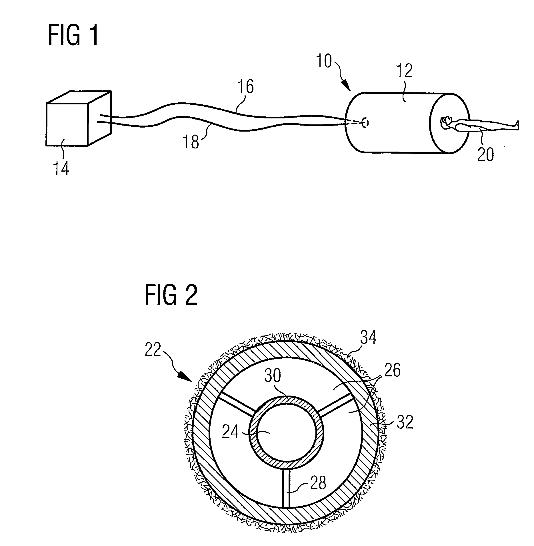
[0019]FIG. 1 shows a basic representation of a magnetic resonant imaging machine system 10 with a cryostat and imaging equipment 12 enclosing a patient 20. Gas transfer hoses 16 and 18 connect the compressor 14 with the equipment 12. An pulsed supply of gas flows from the compressor 14 to a refrigerator, cryostat, or other equipment 12, and back again from the refrigerator, cryostat, or other equipment 12 to the compressor. The present invention is particularly applicable to supply and return hoses used to supply a refrigerator 12 with pulsed or oscillating gas flow from a remo...


PUM


Abstract

A gas transfer hose for connecting a cryogenic apparatus to a superconducting system such as a magnetic resonant imaging system. The improved gas transfer hose, in operation, is quieter than hitherto.

Description

FIELD OF THE INVENTION[0001]The present invention relates to cryogenic assemblies for magnetic resonant imaging systems and the like. In particular, but not necessarily restricted thereto, the present invention relates to a cryogenic hose of the type which is employed to connect a cryogenic compression apparatus to a superconducting system such as a magnetic resonant imaging system.BACKGROUND TO THE INVENTION[0002]In many cryogenic applications components, e.g. superconducting coils for magnetic resonance imaging (MRI), superconducting transformers, generators, electronics, are cooled by keeping them in contact with a volume of liquefied gas (e.g. Helium, Neon, Nitrogen, Argon, Methane), the whole cryogenic assembly being known as a cryostat. In order to operate a superconducting magnet, it must be kept at a temperature below its superconducting transition temperature. For conventional low temperature superconductors, the transition temperature is in the region of 10K, and typically...

Claims


Application Information

Patent Timeline
IPC IPC(8): F17C13/00F16L9/18F16L9/19F16L55/033F16L59/14
CPCF16L55/0336F16L9/19
Inventor CROWLEY, DAVID MICHAEL
Owner SIEMENS MAGNET TECH
Why Eureka
Try Eureka