Air treatment system

a technology of air treatment system and air filter, which is applied in the direction of material analysis using wave/particle radiation, space heating and ventilation details, domestic heating, etc. it can solve the problems of preventing or restricting the uniformity of ultraviolet density in the chamber, occupying a considerable amount of space by the plurality of ultraviolet lamps and the corresponding electrical components, and causing undesirable glow along the ductwork

Active Publication Date: 2008-06-12
HAIER US APPLIANCE SOLUTIONS INC
View PDF23 Cites 14 Cited by
  • Summary
  • Abstract
  • Description
  • Claims
  • Application Information

AI Technical Summary

Benefits of technology

[0004]In one aspect, an air treatment system is provided. The air treatment system includes a housing defining a chamber. The housing further defines an air inlet at a first end portion of the housing and an air outlet at a second end portion of the housing opposing said first end portion. The chamber provides flow communication between the air inlet and the air outlet. At least one ultraviolet lamp is positioned within the chamber. The at least one ultraviolet lamp is positioned about a first axis and includes a first end and a second end spaced with respect to the first end along the first axis. The at least one ultraviolet lamp is configured for facilitating inactivating contaminants within air channeled through the chamber.
[0005]In another aspect, an air treatment system is provided. The air treatment system includes a housing defining a chamber. The housing further defines an air inlet at a first end portion of the housing and an air outlet at a second end portion of the housing opposing the first end portion. The chamber provides flow communication between the air inlet and the air outlet. At least one ultraviolet lamp is positioned within the chamber. The at least one ultraviolet lamp is configured for facilitating inactivating contaminants within air channeled through the chamber. A light trap is coupled to the housing with respect to at least one of the air inlet and the air outlet. The light trap is configured to prevent light generated by the at least one ultraviolet lamp from exiting said housing.
[0007]In still another aspect, a method for assembling an air treatment system is provided. The method includes providing a housing defining a chamber along a first axis. The housing further includes an air inlet at a first end portion of the chamber and an air outlet at a second end portion of the chamber. The chamber defines an air passage providing flow communication between the air inlet and the air outlet. At least one ultraviolet lamp is positioned within the air passage. The at least one ultraviolet lamp is positioned about the first axis and includes a first end and a second end spaced with respect to the first end along the first axis. The at least one ultraviolet lamp is configured for facilitating inactivating contaminants within air channeled through the air passage.

Problems solved by technology

The escaped ultraviolet light may promote the degradation of plastic duct material and may also produce an undesirable glow along the duct work.
Additionally, the plurality of ultraviolet lamps and the corresponding electrical components occupy a considerable amount of space within the chamber and require a sufficiently large air purification apparatus chamber.
Moreover, the arrangement of the ultraviolet lamps and corresponding electrical components prevents or limits a uniform ultraviolet density within the chamber.
To compensate for the nonuniform ultraviolet density within the chamber, an ultraviolet light reflective layer is coated on an inner surface of the chamber to improve the ultraviolet density uniformity, which undesirably increases manufacturing time and / or cost.

Method used


Image

  • Air treatment system
  • Air treatment system
  • Air treatment system

Examples


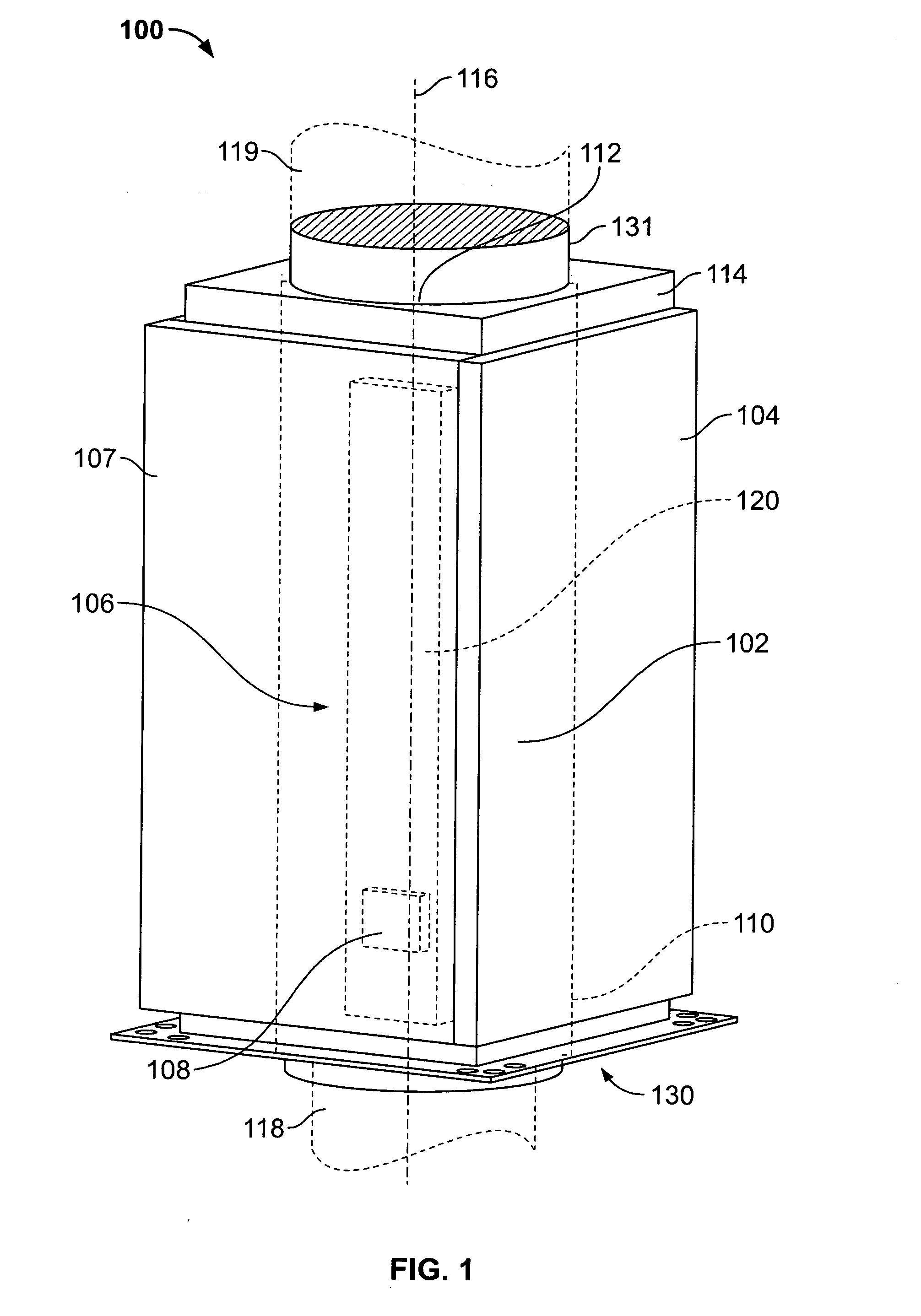
Embodiment Construction

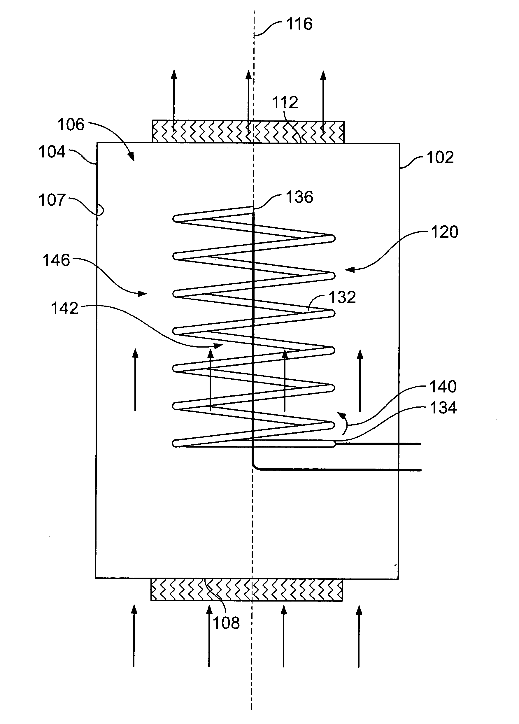
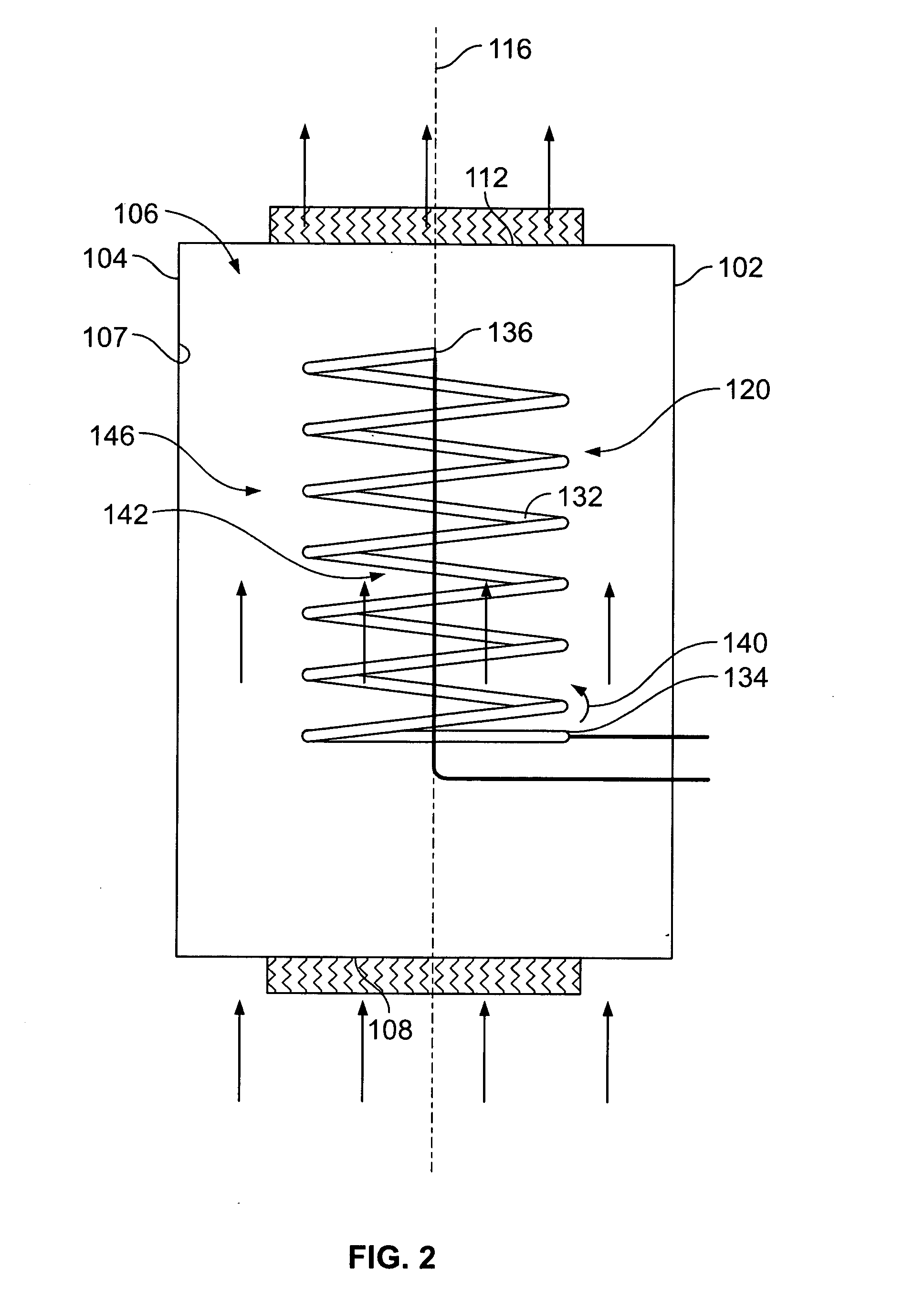
[0013]FIG. 1 is a perspective view of an exemplary air treatment apparatus 100. Air treatment apparatus 100 is suitable for use with any suitable air treatment system including, without limitation, an air conditioning system (not shown), for inactivating and / or removing contaminants such as bacteria and / or microbes within air channeled through air treatment system 100. In one embodiment, air treatment apparatus 100 includes a housing 102 having a generally cylindrical shape that forms a sidewall 104 defining a chamber 106. In alternative embodiment, housing 102 may have any suitable shape forming any suitable number of sidewalls. Housing 102 also defines an air inlet 108 at a first end 110 of chamber 106 and an air outlet 112 at a second end 114 of chamber 106 opposing first end portion 110. Chamber 106 extends along a longitudinal central axis 116 of housing 102 between air inlet 108 and air outlet 112 to provide air flow communication therebetween. Air inlet 108 is coupled in flow...


PUM

PropertyMeasurementUnit
angleaaaaaaaaaa
angleaaaaaaaaaa
angleaaaaaaaaaa

Abstract

An air treatment system includes a housing defining a chamber, and an ultraviolet lamp positioned within the chamber. The housing further defines an air inlet at a first end portion of the housing and an air outlet at a second end portion of the housing opposing the first end portion. The chamber provides flow communication between the air inlet and the air outlet. At least one ultraviolet lamp is positioned within the chamber. The at least one ultraviolet lamp is positioned about a first axis and includes a first end and a second end spaced with respect to the first end along the first axis. The at least one ultraviolet lamp is configured for facilitating inactivating contaminants within air channeled through the chamber.

Description

BACKGROUND OF THE INVENTION[0001]This invention relates generally to air purification and treatment and, more particularly, to systems and methods for purifying and treating air.[0002]At least some conventional air purification apparatus include a housing defining a chamber. An inlet air duct is positioned at a first end of the chamber and an outlet air duct is positioned at an opposing second end of the chamber. A plurality of ultraviolet lamps are positioned within the chamber. Each lamp is coupled to a lamp holder mounted within the chamber to hold the lamp stationary within the chamber. A corresponding ballast and harness electrically couples the lamp to an electrical source for energizing the lamp. During operation, unpurified air is channeled through the chamber. The ultraviolet lamps are energized to generate ultraviolet light, which purifies the air as the air moves through the chamber. In at least some conventional air purification apparatus, ultraviolet light is able to tr...

Claims


Application Information

Patent Timeline
Patent Type & Authority Applications(United States)
IPC IPC(8): B01D49/00B23P11/00
CPCY10T29/49826A61L9/20F24F8/22F24F13/082
Inventor SUBBARAO, GAUTAMWILSON, MARK WAYNEJOSHI, ANAND GANESHUMAKANTHAN, HEMACHANDRANVAIDYANATHAN, RAMANTH
Owner HAIER US APPLIANCE SOLUTIONS INC
Why Eureka
Try Eureka