Circular secondary clarifier for wastewater treatment and an improved s0lids-liquid separation process thereof

a secondary clarifier and wastewater treatment technology, applied in separation processes, liquid displacement, sedimentation settling tanks, etc., can solve the problems of reducing the concentration of underflow solids, deteriorating the quality of treated effluent, and thickening solids, so as to achieve the effect of substantially discharging hydraulic energy

Active Publication Date: 2008-06-12
COUNCIL OF SCI & IND RES
View PDF18 Cites 7 Cited by
  • Summary
  • Abstract
  • Description
  • Claims
  • Application Information

AI Technical Summary

Benefits of technology

[0025]Provision of a circular baffle wall as a precautionary measure, to prevent escape of solids, in case some air bubbles find way into the plume and burst at the top, thereby disturbing the plume. The baffle wall helps in containing the plume within its diameter under such circumstances, thereby restricts escape of solids along with the treated effluent.
[0026]In an embodiment of the present invention, a circular secondary clarifier connected through a low level inlet (13), capable of providing steady uniform flow being gradually enlarged at the outlet (14), is capable of dissipating the hydraulic energy substantially.

Problems solved by technology

Since the difference in the density of biological solids and wastewater is very less, the solids remain in suspension, and are carried away along with the outgoing wastewater, thereby deteriorating the treated effluent quality.
This in turn affects the thickening of solids and reduces the underflow solids concentration.
However, in the conventional clarifiers it is not feasible to provide higher ranges for design parameters (SLR, SOR) due to the problem of effective solids-liquid separation.
External addition of solids in the raw wastewater not only increases the size of clarifiers to accommodate increased sludge blanket, but also requires large sludge dewatering facilities.
Further, the management of solids handling and disposal becomes tedious and means additional recurring cost due to increase in quantity of sludge generated, whereas the clarifier described in the present invention, can be used for primary clarification of raw wastewater without addition of fly ash.
This system is only suitable for small-scale treatment plants, since such an installation is not feasible for large-scale wastewater treatment systems.

Method used


Image

  • Circular secondary clarifier for wastewater treatment and an improved s0lids-liquid separation process thereof
  • Circular secondary clarifier for wastewater treatment and an improved s0lids-liquid separation process thereof
  • Circular secondary clarifier for wastewater treatment and an improved s0lids-liquid separation process thereof

Examples


example-1

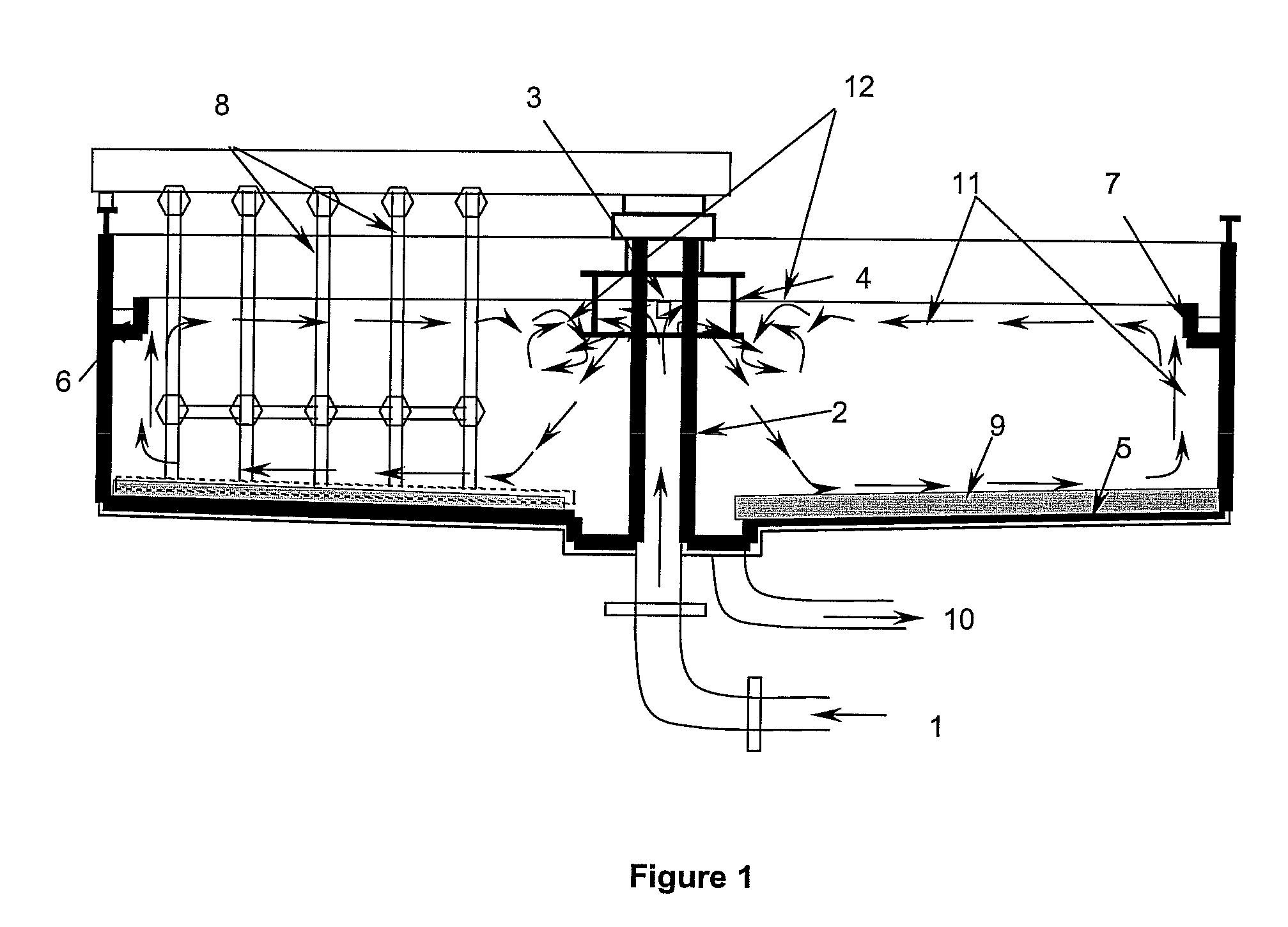
[0045]An optimized bench scale reactor of improved circular secondary clarifier was prepared using transparent Perspex cylinder of thickness 6 mm and internal diameter 430 mm and polycarbonate flexible sheet of thickness 2 mm. The influent pipe was made of glass tube of internal diameter 4 mm and thickness 1 mm and the tube diameter was gradually enlarged to 12 mm diameter over a length of 30 mm. The bottom of reactor was made of flexible polycarbonate sheet giving a slope of 1 in 10, away from the center. The water depths in the reactor at center and edges were 15 and 18 cm, respectively. The surface area of reactor was 0.1452 m2 and the volume was 24 L. The effluent collection channel called as launder was made of transparent Perspex ring and flexible polycarbonate sheet. The internal and external diameters of the ring were 432 and 460 mm respectively and the launder side wall was made of polycarbonate sheet of thickness 2 mm. A treated effluent outlet made of glass tube of intern...

example 2

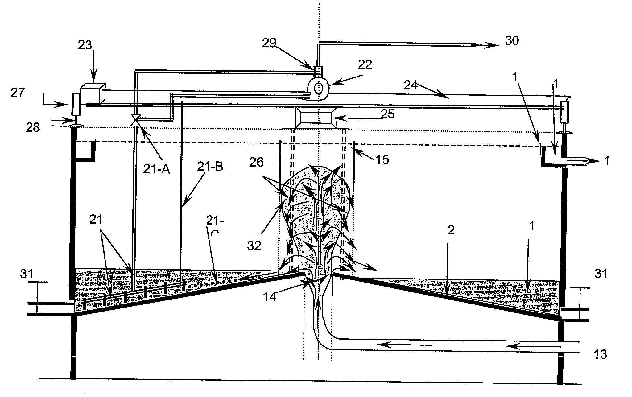
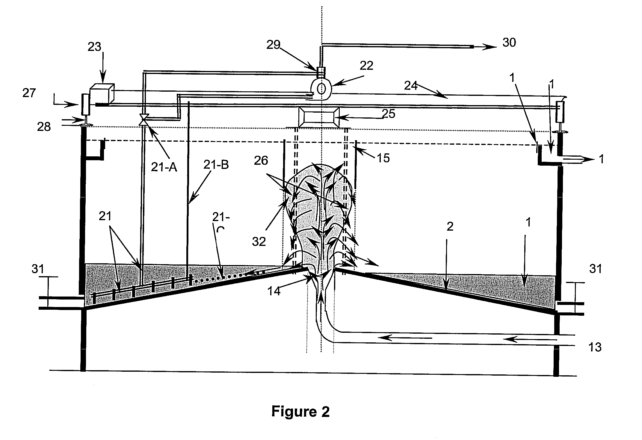
[0046]The wastewater containing MLSS enters in clarifier through a low level inlet (13) that is gradually enlarged at the outlet (14) to distribute the wastewater uniformly all over the bottom (20). Gradual increase in pipe diameter reduces velocity of the incoming wastewater thereby reducing hydraulic energy and prevents jetting thus uniformly distributing wastewater at the bottom (20). The hydraulic energy of the incoming wastewater is substantially reduced due to gradual increase in feed pipe diameter and liquid level (33) starts increasing in the clarifier allowing the solids (34) to be accumulated at the bottom (20) towards the outer edges of clarifier. When the liquid level (35) starts rising the solids present in wastewater collide with each other just above the gradually enlarged outlet (14), thereby undergoing natural flocculation and form bigger solids referred to as flocs. The flocs further form a sludge cloud referred to as plume (36), which rises vertically upwards to s...

example 3

[0047]The reactor was subjected to various solids concentrations 500-5000 mg / L, and flow rates giving variable HRT ranging from 1.0-1.5 hrs. The various parameters, viz. effluent SS and BOD, Return activated sludge (RAS) concentration, SS profile and particle size analysis at various depths along the radius of the clarifier were carried out to arrive at the optimized performance of the secondary clarifier. Table 1 shows the performance of an improved bench scale secondary clarifier and Table 2 presents a comparison of an improved and conventional secondary clarifier after scale up. The effluent parameters with respect to SS, as shown in Table 1 are well within the prescribed Standards and the RAS concentrations are also high as compared to conventional clarifier. The effluent SS concentrations obtained from improved clarifier are less than those obtained from settling studies carried out in 1 L cylinder, which clearly indicates that the clarifier has capability of providing natural ...


PUM

PropertyMeasurementUnit
Hydraulic retention timeaaaaaaaaaa
concentrationaaaaaaaaaa

Abstract

The improved circular secondary clarifier of the present invention requires less surface area and low HRT and provides efficient solids-liquid separation. The improved clarifier has better SS and BOD reduction and provides high under flow solids concentrations, as compared to conventional secondary clarifiers. The improved clarifier is even capable of treating wastewaters containing low MLSS concentration. One of the biggest advantages of improved clarifier is that it does not require a separate sump cum pump house as it removes the settled sludge using suction mechanism thereby reduces capital and recurring cost. Further, it provides natural flocculation, which is essential for agglomeration of solids and increases particle size referred to as ‘floc’ and eliminates provision for a separate flocculation facility thereby reduces capital and recurring costs.

Description

FIELD OF INVENTION[0001]The present invention relates to “An Improved Circular Secondary Clarifier for Wastewater Treatment and an Improved Solids-liquid Separation Process Thereof”. The improved circular secondary clarifier of the present invention enables treatment of wastewaters having suspended solids (SS) concentration in the range 500-5000 mg / l and above, and provides improved solids-liquid separation and enhanced biochemical oxygen demand (BOD) reduction with reduced surface area and low hydraulic retention time (HRT). The improved circular secondary clarifier capable of removing up to 99% of SS also ensures, high under flow solids concentration in the range 15000-17000 mg / l, to be returned to aeration tank using sludge removal suction mechanism. The improved circular secondary clarifier also increases particle size referred to as ‘floc’ through natural flocculation and does not require separate flocculation facility.BACKGROUND AND PRIOR ART[0002]A conventional circular secon...

Claims


Application Information

Patent Timeline
Patent Type & Authority Applications(United States)
IPC IPC(8): B01D43/00
CPCB01D21/0042B01D21/0087B01D21/245B01D21/2427B01D21/06
Inventor POPHALI, GIRISH RAMESHNANDY, TAPASKAUL, SANTOSH NARAINDEVOTTA, SUKUMAR
Owner COUNCIL OF SCI & IND RES
Why Eureka
Try Eureka