Device for detecting the state of steel-reinforced concrete construction parts

US20080136425A1Inactive Publication Date: 2008-06-12BRAUNSCHWEIG UNIVERSITY OF TECHNOLOGY

Image

  • Device for detecting the state of steel-reinforced concrete construction parts
  • Device for detecting the state of steel-reinforced concrete construction parts
  • Device for detecting the state of steel-reinforced concrete construction parts

Examples


first embodiment

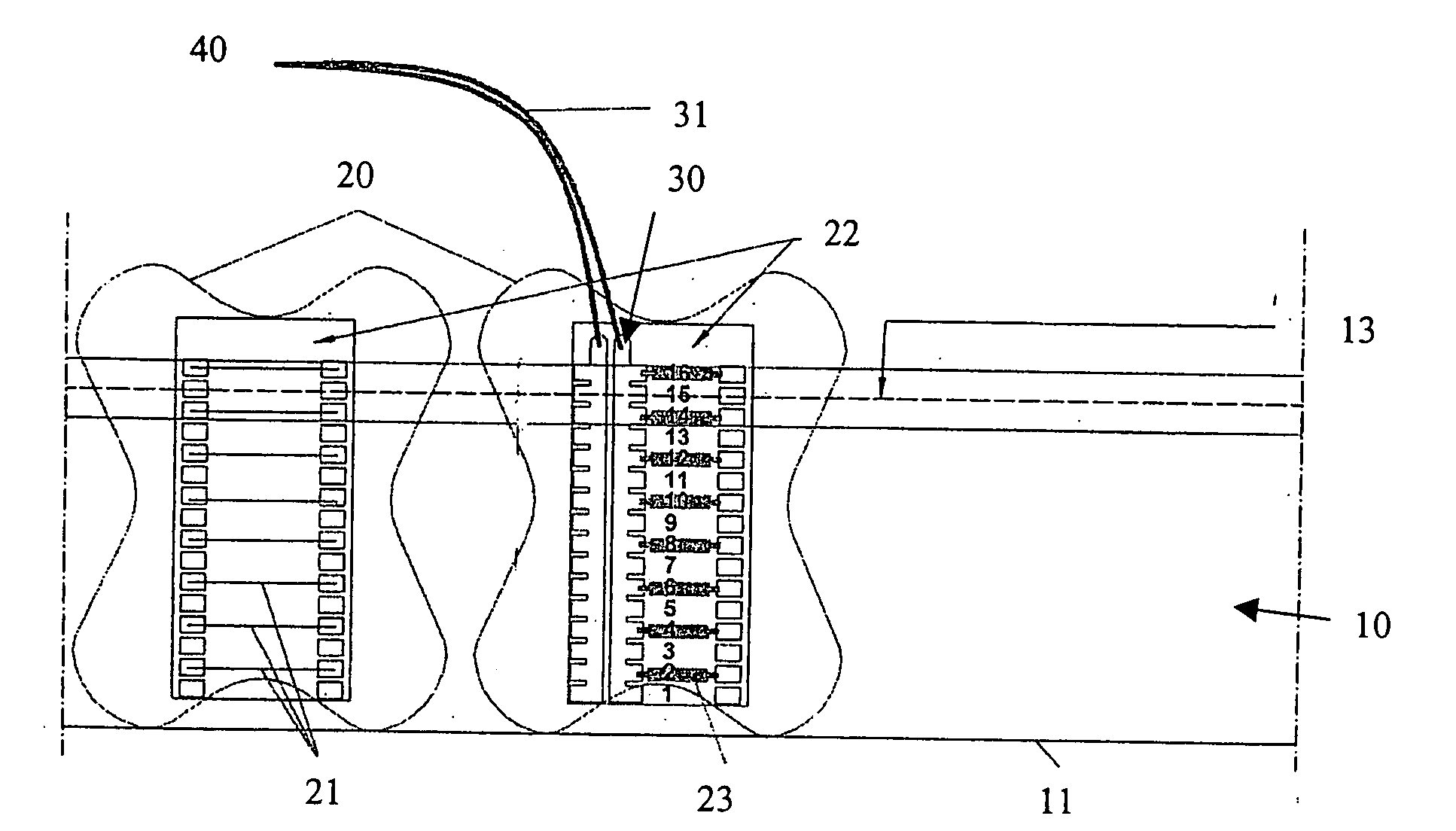
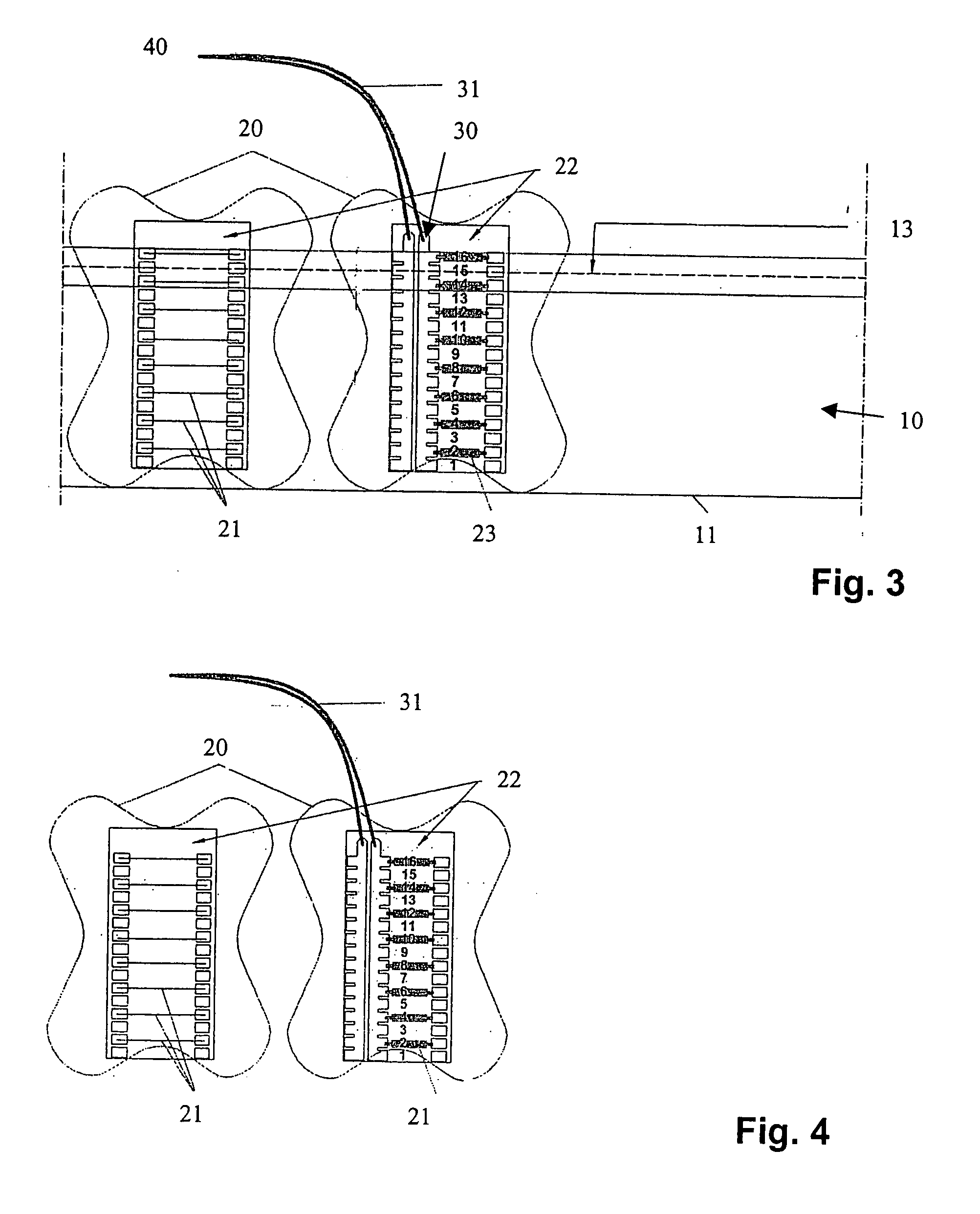
[0053]In FIG. 3, the invention is shown schematically in more detail. Here, an embodiment is involved that is suitable for initial installation. This means that this device for detecting the state of steel-reinforced concrete construction parts 10 will be incorporated from the beginning by sealing it in during the production of the concrete construction part.

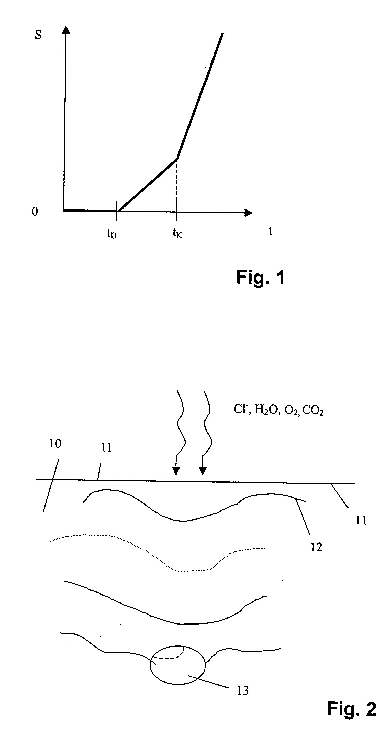
[0054]A concrete construction part 10 in turn can be seen schematically. A surface 11 of concrete construction part 10 is shown at the bottom in this case and the concrete construction part 10 can continue toward the top in the drawing to an extent that is selected arbitrarily.

[0055]In concrete construction part 10 there is found a reinforcement bar 13, which in this case—as also in practice—extends frequently inside it, usually parallel to the surface 11 of the concrete construction part 10. The progression of a depassivation front from the surface 11 of the construction part into the concrete construction part 10 will now be m...

second embodiment

[0069]a device according to the invention is shown in FIG. 5. This embodiment is suitable for the case of later installation. That is, it is frequently also of interest to equip an already existing concrete construction part 10 with this device at a later time for such detection of [corrosion] states. In this case, a drilled hole 15 must be introduced into the inside of concrete construction part 10 through the surface 11. Insofar as this is possible, this drilled hole should not destroy or attack the steel reinforcement 13 itself, but should be suitable for introducing the device for detecting the state of the steel-reinforced concrete construction part 10 according to the invention to a sufficient depth.

[0070]Such a device is prefabricated in this case, whereby a serial production is possible without anything further. Here, a mortar pin 25 is used as support 20, and this can be particularly well recognized in FIG. 6. This cement mortar pin 25 is approximately semi-cylindrical and ...


PUM


Abstract

A device for detecting the state of steel-reinforced concrete construction parts, having one or more sensor wires disposed at different distances from a surface of the concrete construction part. The wires are subjected to the corroding influence of the environment of the concrete construction part. The device also includes a measuring instrument, which measures the volume resistance of the sensor wires and an evaluating device, which can supply the measurement values of the measuring instrument either permanently and / or when called up, and which, evaluating from these values, draws conclusions on the depth-dependent corrosion state of the concrete construction part.

Description

TECHNICAL FIELD[0001]The invention relates to a device for detecting the state of steel-reinforced concrete construction parts.BACKGROUND OF THE INVENTION[0002]The corrosion of steels in concrete is one of the most important causes of damage in steel-reinforced and pre-stressed concrete structures. The considerable dangers that can ensue from damaged concrete structures lead to the fact that there is an interest in knowing how far possible damage of the steel in concrete has progressed.[0003]The growing trend toward preservation of structures and the knowledge that a timely recognition of damage makes possible a prevention or suitable corrective measures and, in any case, can reduce the danger of damage to the surroundings of the structure intensifies interest in better measurement methods.[0004]In the past, it has generally been attempted to establish the state of corrosion of steel reinforcements of solid structures by a visual inspection of accessible regions of the surface of th...

Claims


Application Information

Patent Timeline
12 Jun 2008
Publication
US20080136425A1
IPC
G01R27/08
CPC
G01N17/04
Inventors
HOLST, ALEXANDER; BRUDER, STEFAN