
Single-fault laser driver control for optical mouse

a laser driver and optical mouse technology, applied in the field of optical pointing devices, can solve problems such as difficult control and unoptimized approach, and achieve the effect of good system performan

Active Publication Date: 2008-06-12
EM MICROELECTRONIC-MARIN
View PDF10 Cites 4 Cited by
  • Summary
  • Abstract
  • Description
  • Claims
  • Application Information

AI Technical Summary

Benefits of technology

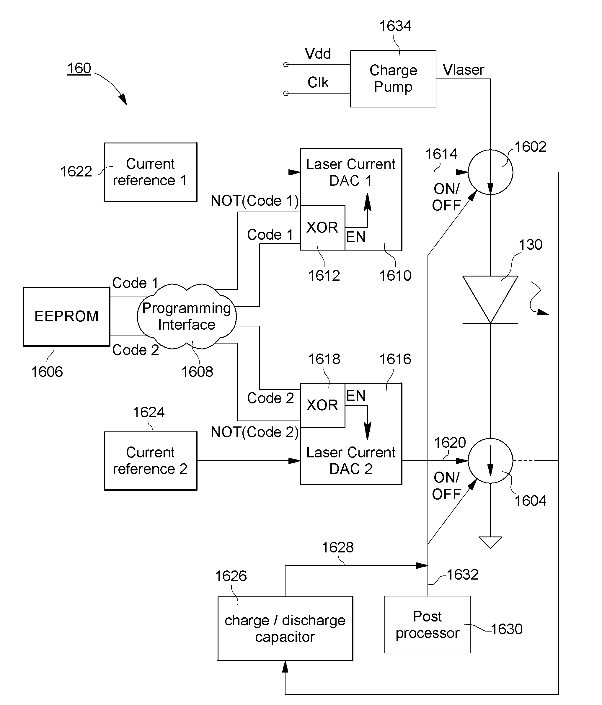
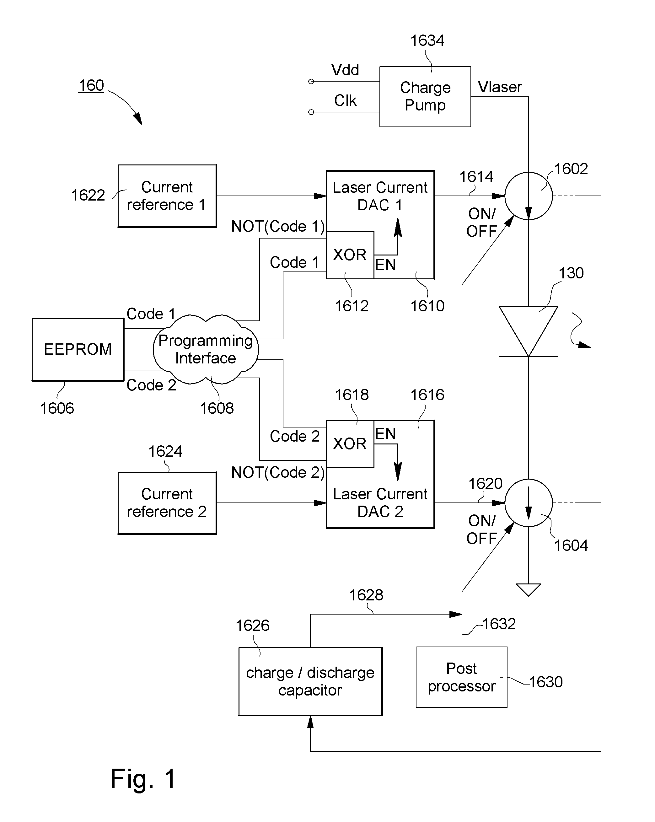
[0008]One goal of the present invention is thus to implement an optical pointing device in order to overcome aforecited drawbacks by preventing a single failure within the laser driver path to result in a harmful laser output power. For that purpose, the invention concerns an optical pointing device comprising a coherent light source for illuminating a surface portion with radiation, a driver of the coherent light source for controlling coherent light emissions, a photodetector device responsive to radiation reflected from the illuminated surface portion, and processing means for determining, based on the photodetector device response, a measurement of relative motion between the optical pointing device and the illuminated portion of the surface, wherein the coherent light source driver is a fault-tolerant driver comprising redundant power control means for limiting the output power of coherent light emissions. Thus, this invention allows the laser power to be programmed at the factory very near the maximum allowed output power with respect to safety requirements. Through monitoring and controlling of the coherent light source driver, the single point failure requirements and good system performances are simultaneously achieved.

Problems solved by technology

These safety requirements eventually along with additional system requirements create a difficult control problem in which the optical safety and system operation must exist simultaneously.
However, this approach is not optimum because there is not sufficient light recovered by the photodetector to support high tracking speeds and / or high signal to noise ratio.

Method used


Image

  • Single-fault laser driver control for optical mouse
  • Single-fault laser driver control for optical mouse
  • Single-fault laser driver control for optical mouse

Examples


Embodiment Construction

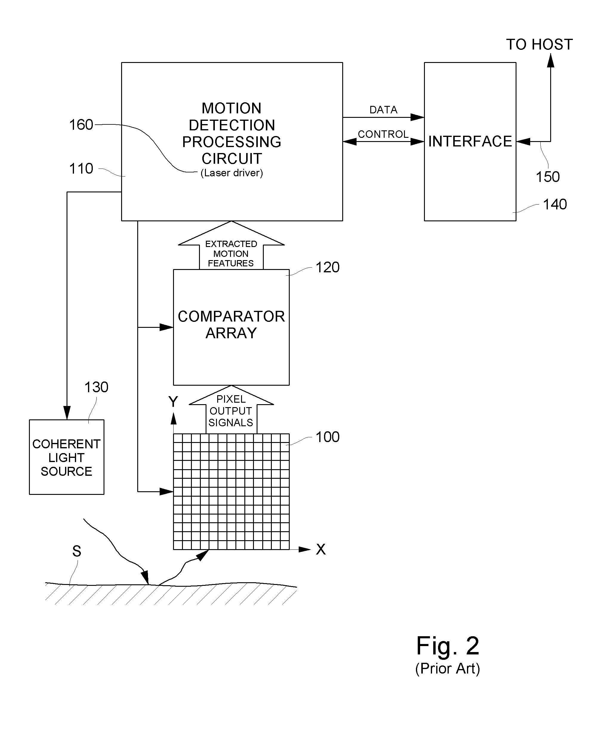
[0013]The following description given by way of a non limiting example concerns an optical pointing device which comprises a coherent light source (for instance a laser diode) for illuminating a portion of a surface with radiation, a driver of the coherent light source (for instance a so-called “laser driver”) for controlling coherent light emissions, a photodetector device responsive to radiation reflected from the illuminated surface portion and processing means for determining, based on the photodetector device response, a measurement of relative motion between the optical pointing device and the illuminated portion of the surface, as generally represented in FIG. 2 and more particularly relates to the laser driver which will be detailed in relation with FIG. 1. It is to be noted that this laser driver may be implemented directly within the processing means or, alternatively, separately from them.

[0014]FIG. 1 shows a schematic diagram of a fault tolerant laser driver according to...


PUM


Abstract

The invention concerns an optical pointing device comprising a coherent light source for illuminating a surface portion with radiation, a driver of the coherent light source for controlling coherent light emissions, a photodetector device responsive to radiation reflected from the illuminated surface portion, processing means for determining, based on the photodetector device response, a measurement of relative motion between the optical pointing device and the illuminated portion of the surface, wherein the coherent light source driver is a fault-tolerant driver comprising redundant power control means for limiting the output power of coherent light emissions.

Description

FIELD OF THE INVENTION[0001]The present invention generally relates to optical pointing devices, in particular for controlling the position of a cursor on a screen, such as the display of a personal computer, workstation or other computing devices having a graphic user interface. Such optical pointing devices may for instance include mice, trackballs and other computer peripherals for controlling the position of a cursor on a display screen.[0002]The present invention more particularly relates to the field of optical pointing devices which comprise a coherent light source for illuminating a portion of a surface with radiation, a driver of the coherent light source for controlling coherent light emissions, a photodetector device responsive to radiation reflected from the illuminated surface portion and processing means for determining, based on the photodetector device response, a measurement of relative motion between the optical pointing device and the illuminated portion of the su...

Claims


Application Information

Patent Timeline
Patent Type & Authority Applications(United States)
IPC IPC(8): G06F3/033G06F3/038
CPCG06F3/0317
Inventor GROSJEAN, SYLVAINWILLEMIN, MICHELLAUFFENBURGER, JAMES HAROLDAFRIAT, GILBUESCHER, KEVIN SCOTTBIEBER, LAWRENCE
Owner EM MICROELECTRONIC-MARIN
Learn More