Pumping schemes for x-ray tubes with ferrofluid seals

a technology of ferrofluid seals and x-ray tubes, which is applied in the field of x-ray tubes, can solve the problems of increasing acoustic noise, increasing stress on the rotor, and increasing the operating conditions of newer generation x-ray tubes, so as to mitigate the ionizable gas load

Active Publication Date: 2008-06-12
GENERAL ELECTRIC CO
View PDF6 Cites 9 Cited by
  • Summary
  • Abstract
  • Description
  • Claims
  • Application Information

AI Technical Summary

Benefits of technology

[0009]The present invention provides an apparatus for mitigating an ionizable gas load on an x-ray tube that overcomes the aforementioned drawbacks. A pressure reducing device is fluidically coupled to a high vacuum region of the x-ray tube to mitigate the ionizable gas load therein that emits from or through the ferrofluid seal.

Problems solved by technology

This places stringent demands on the bearing assembly, which typically includes tool steel ball bearings and tool steel raceways positioned within the vacuum region, thereby requiring lubrication by a solid lubricant such as silver.
Wear of the lubrication and loss thereof from the bearing contact region increases acoustic noise and slows the rotor during operation.
In addition, the operating conditions of newer generation x-ray tubes have become increasingly aggressive in terms of stresses because of g forces imposed by higher gantry revolution speeds and higher anode rotational speeds.
Furthermore, such bearings may be larger than those typically used on the vacuum side.
Ionizable gases that transport through the seal, when exposed to the high voltage environment of an x-ray tube, can lead to ionization failure of the x-ray tube.
Likewise, a gas evaporated from the hydrocarbon-based or fluorocarbon-based oil used to make the ferrofluid that occupies the annular regions of the ferrofluid assembly may pass into the vacuum region, leading eventually to ionization failure of the x-ray tube.

Method used


Image

  • Pumping schemes for x-ray tubes with ferrofluid seals
  • Pumping schemes for x-ray tubes with ferrofluid seals
  • Pumping schemes for x-ray tubes with ferrofluid seals

Examples


Embodiment Construction

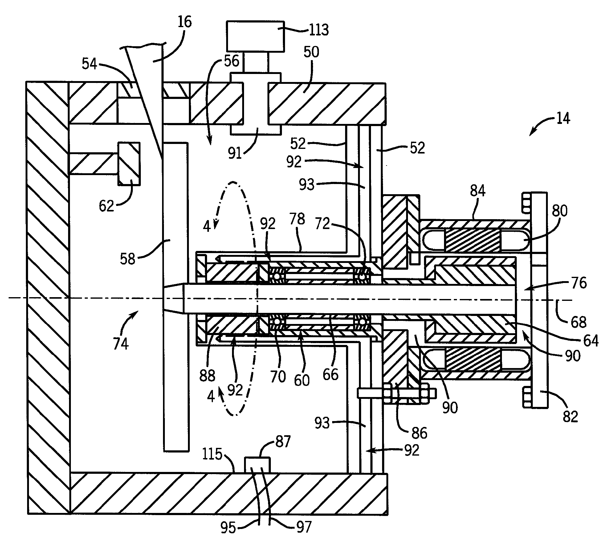
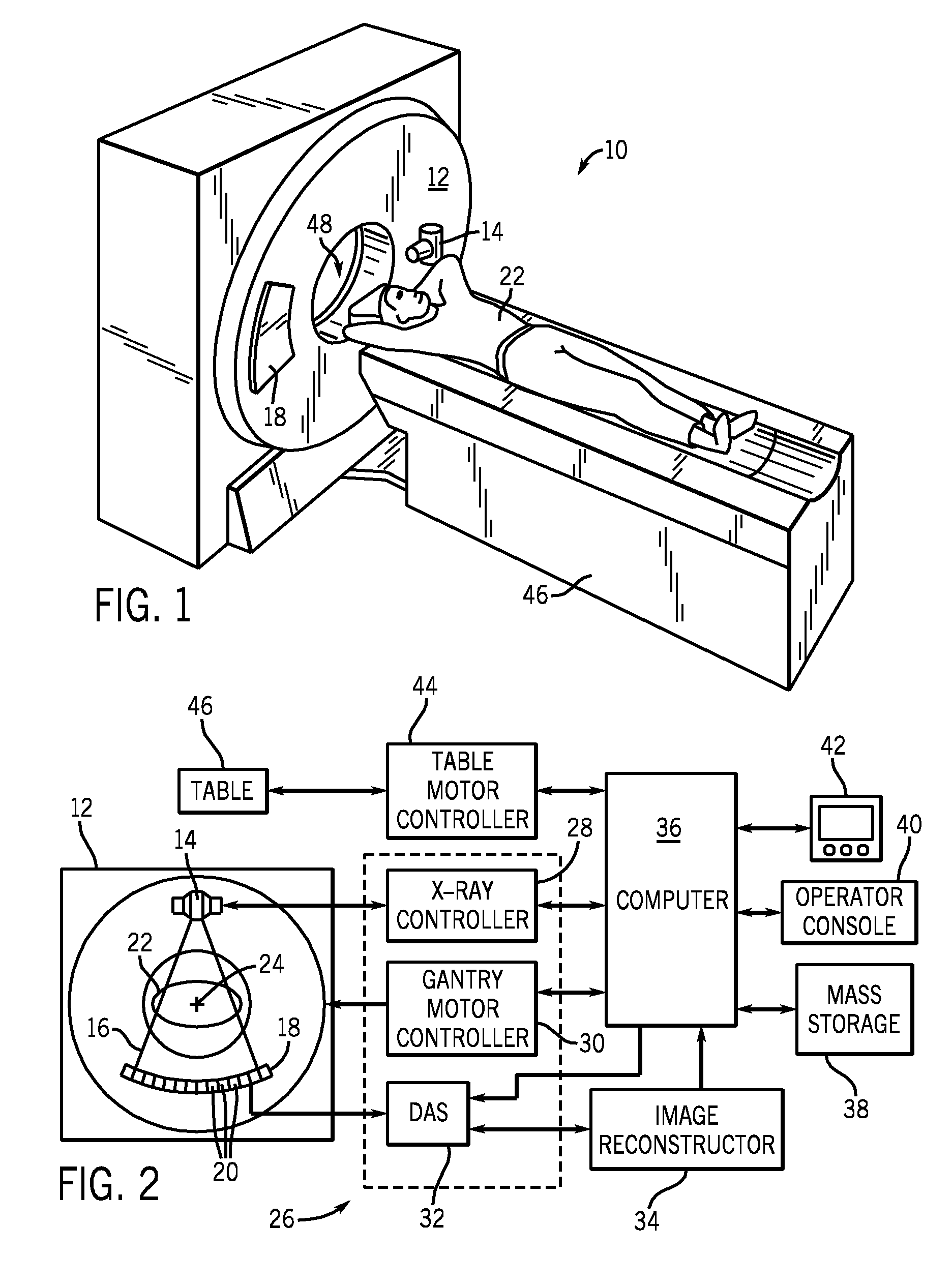
[0023]The operating environment of the present invention is described with respect to the use of an x-ray tube as used in a computed tomography (CT) system. However, it will be appreciated by those skilled in the art that the present invention is equally applicable for use in other systems that require the use of an x-ray tube. Such uses include, but are not limited to, x-ray imaging systems (for medical and non-medical use), mammography imaging systems, and radiographic (RAD) systems.

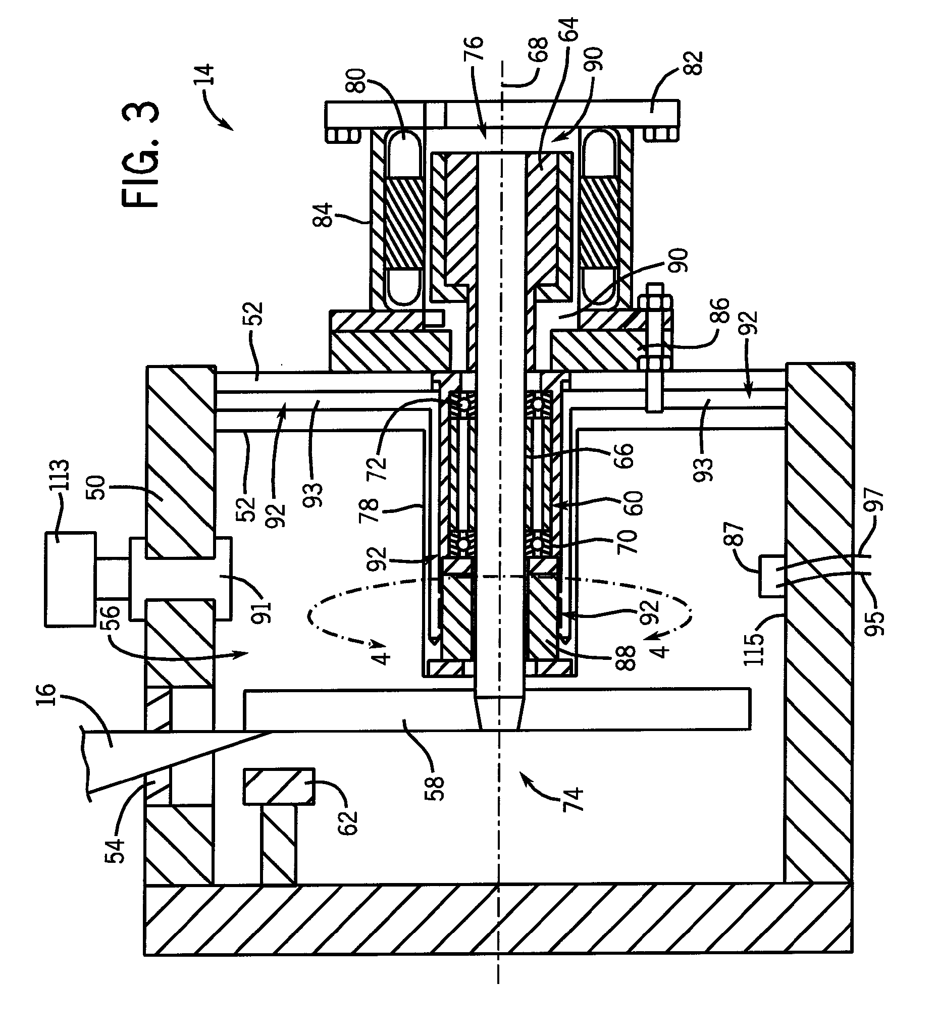
[0024]Moreover, the present invention will be described with respect to use in an x-ray tube. However, one skilled in the art will further appreciate that the present invention is equally applicable for other systems that require operation of a high vacuum environment that experiences a degradation of performance due to the presence of ionizable gases, the systems of which that could benefit from a reduction of an ionizable gas load. The present invention will be described with respect to a “third gene...


PUM


Abstract

A system for mitigating a gas load imposed upon a high vacuum chamber, thereby reducing the overall pressure, includes a device mounted onto a rotating gantry. The device has a first chamber enclosing a high vacuum and a first region in which anode bearings are positioned. A rotatable shaft has a first portion extending into the first chamber and a second portion extending into the first region. A ferrofluid seal is positioned about the rotatable shaft and positioned between the first portion and the second portion, the ferrofluid seal fluidically separating the first chamber from the first region. At least one pressure-reducing unit is fluidically connected to the first chamber.

Description

BACKGROUND OF THE INVENTION[0001]The present invention relates generally to x-ray tubes and, more particularly, to mitigating a gas load on an x-ray tube chamber having a shaft of an anode passing through a ferrofluid seal.[0002]X-ray systems typically include an x-ray tube, a detector, and a bearing assembly to support the x-ray tube and the detector. In operation, an imaging table, on which an object is positioned, is located between the x-ray tube and the detector. The x-ray tube typically emits radiation, such as x-rays, toward the object. The radiation typically passes through the object on the imaging table and impinges on the detector. As radiation passes through the object, internal structures of the object cause spatial variances in the radiation received at the detector. The detector then emits data received, and the system translates the radiation variances into an image, which may be used to evaluate the internal structure of the object. One skilled in the art will recog...

Claims


Application Information

Patent Timeline
Patent Type & Authority Applications(United States)
IPC IPC(8): H01J35/20F16J15/43
CPCF16J15/43H01J35/101H01J2235/108H01J2235/1066H01J2235/1046H01J35/1017
Inventor GADRE, ANIRUDDHA DATTATRAYAHALLMAN, DARREN LEEPRICE, JOHN SCOTTRATZMANN, PAUL M.ROFFERS, RICHARD MICHAELSMITH, WALTER JOHN
Owner GENERAL ELECTRIC CO
Why Eureka
Try Eureka