Method of non-destructively testing a work piece and non-destructive testing arrangement

a work piece and non-destructive testing technology, applied in the direction of instruments, furniture, specific gravity measurement, etc., can solve the problems of reducing flexibility, causing risk of constraints, and difficult to achieve a force-fit connection between all inner components

Inactive Publication Date: 2008-06-19
SIEMENS GAMESA RENEWABLE ENERGY AS
View PDF19 Cites 35 Cited by
  • Summary
  • Abstract
  • Description
  • Claims
  • Application Information

AI Technical Summary

Benefits of technology

[0065]The combination of an ultrasonic testing probe with a positioning system allows for assigning the measurement signals Mi to a position {right arrow over (r)}i at the work piece by means of the cartography unit. Thus, a map about the material properties of the work piece can be obtained. This map can be used as a basis for quality control of the work piece, because measurement data recorded at different times can be compared with each other.

Problems solved by technology

These requirements are difficult to reach.
This arrangement requires the positioning of the structure to be tested in a specific fixture, which reduces flexibility and causes risk of constraints.
Such wind turbines typically have a rotor with a diameter up to 130 m. Especially the rotor blades are exposed to enormous load changes.
During the manufacturing process it is difficult to achieve a force-fit connexion between all inner components, for example between the upper and lower housing.
Thereby air inclusions may occur, which may decrease the stability of the rotor blade.
In this case delaminations can occur or cracks may be formed, especially at high loads.
In this case it is not possible directly to compare the material properties of the rotor blades after manufacturing and after mounting onto the wind turbine.

Method used


Image

  • Method of non-destructively testing a work piece and non-destructive testing arrangement
  • Method of non-destructively testing a work piece and non-destructive testing arrangement
  • Method of non-destructively testing a work piece and non-destructive testing arrangement

Examples


first embodiment

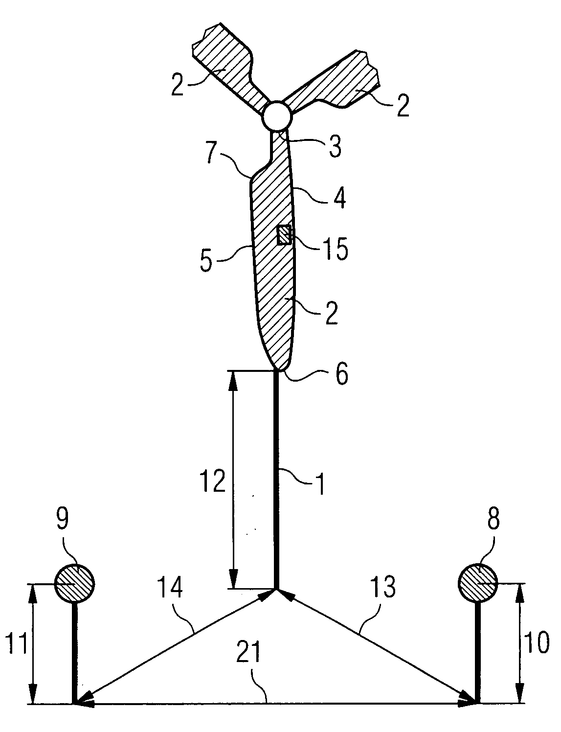
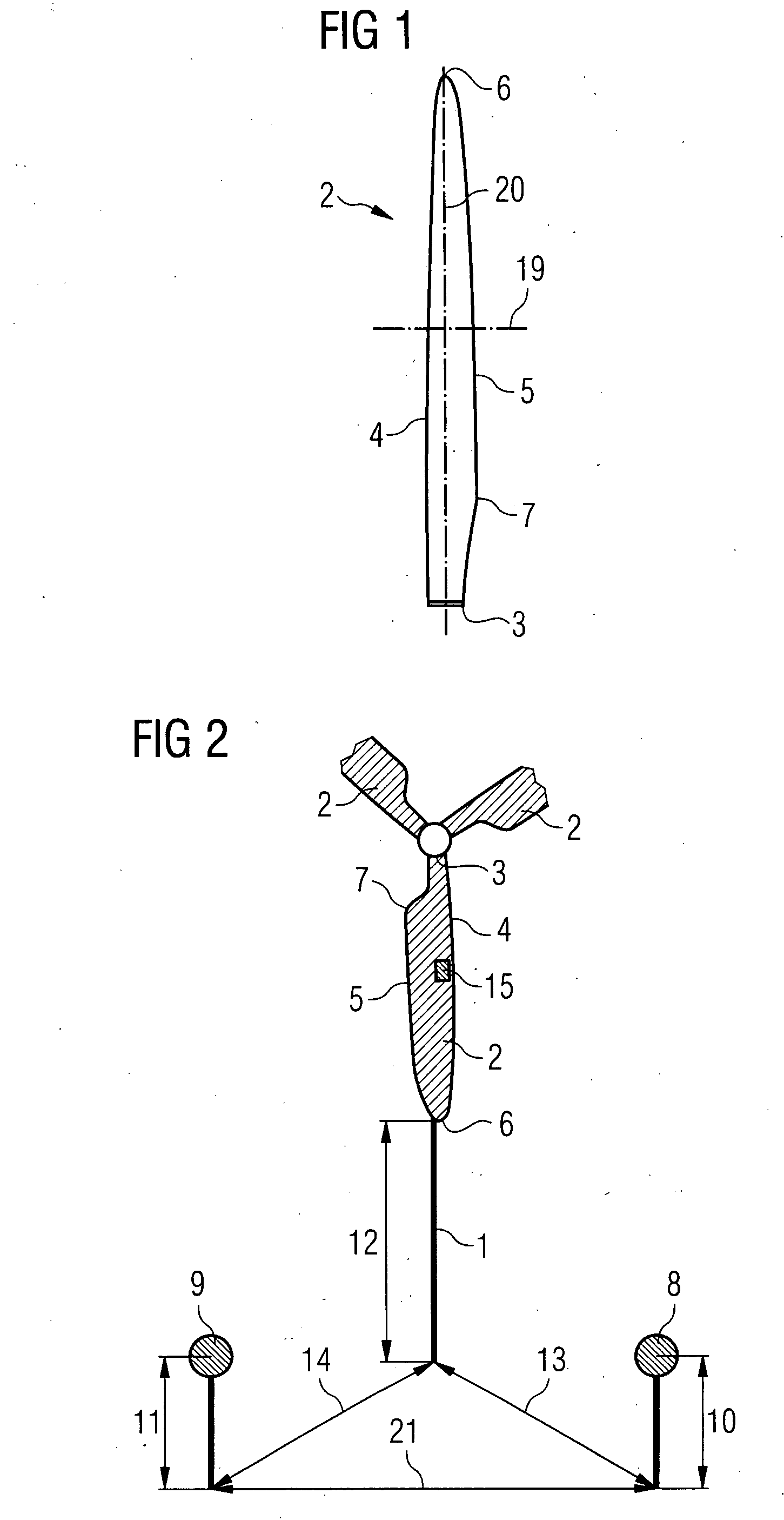
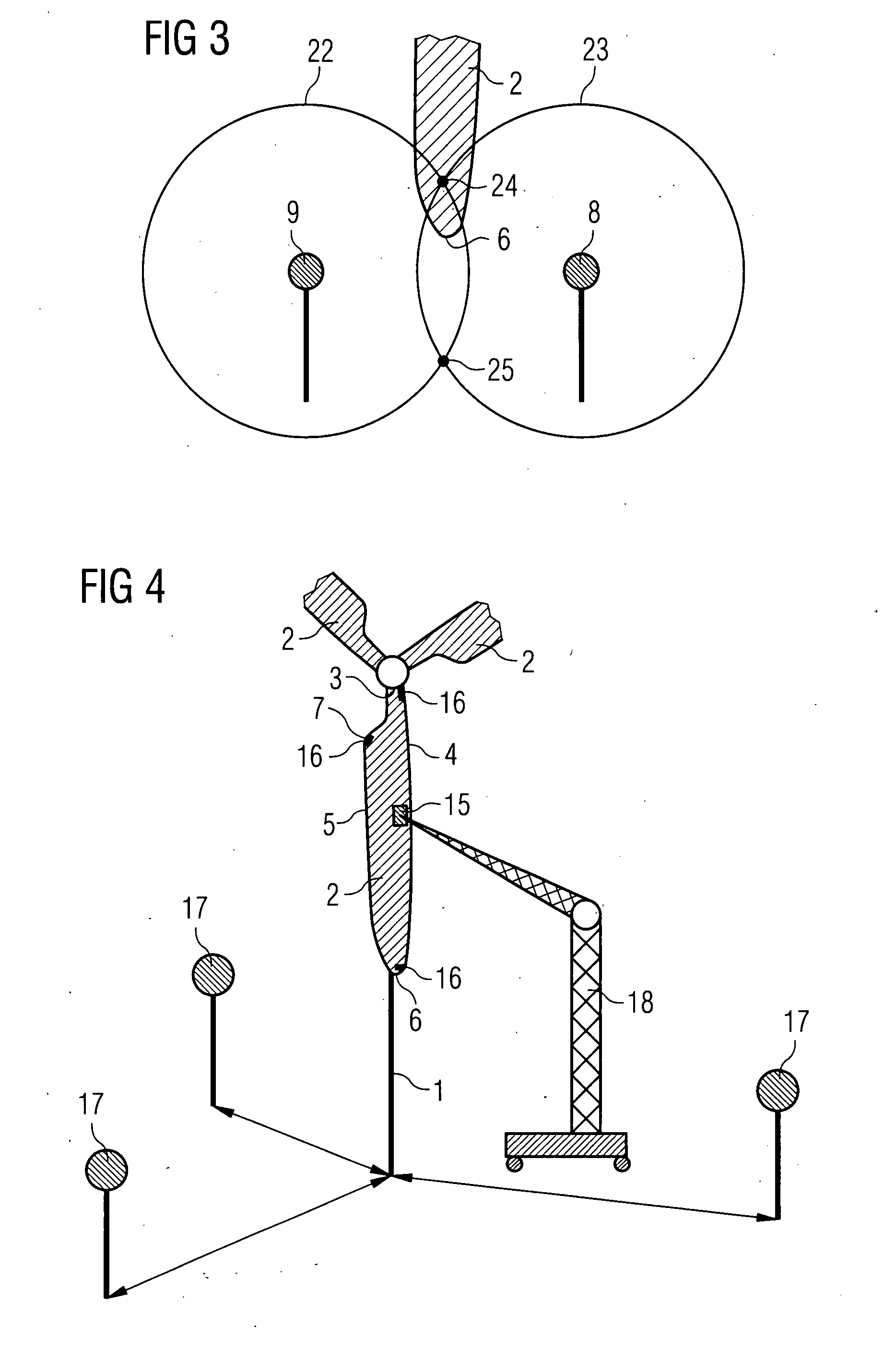
[0076]the inventive method will now be described in more detail with respect to FIGS. 2 and 3. FIG. 2 schematically shows a wind turbine (1) equipped with three wind turbine blades (2) in the field in a perspective view. Characteristic geometrical features of a wind turbine blade are the root (3), the leading edge (4), the trailing edge (5), the tip (6) and the shoulder (7).

[0077]The exact size and shape of the wind turbine blade is either known from the manufacturer or the characteristic features of the blade were measured or scanned by a local positioning system before mounting the blade on the wind turbine. As a frame of reference for all subsequent measurements the location of the span line in the blade root is used as origin and the plane containing the span line (20) and the chord line (19) in the root are used in the present embodiment. However, other origins than the root can be used as well.

[0078]Now one side of the blade is to be two-dimensionally scanned by a non-destruct...

third embodiment

[0089]Now the present invention will be described with reference to FIGS. 5 to 8. In the FIGS. 5 to 8 corresponding elements are designated with the same reference numerals.

[0090]FIG. 5 schematically shows a system for acoustically testing a rotor blade 151. The inventive system comprises an ultrasonic testing probe 120 which is designed as an ultrasonic sensor wheel, a positioning system 130 and a cartography unit 140. In the present embodiment the positioning system 130 comprises four transponders 131a, 131b, 131c, 135. Three transponders 131a, 131b, 131c of the four transponders 131a, 131b, 131c, 135 have a constant distance to each other and establish a frame of reference which is illustrated in FIG. 1 as a coordinate system 180 with axes x, y, and z. The axes x, y, and z are perpendicular to each other.

[0091]The rotor blade 151 is stationary placed in the coordinate system 180. The ultrasonic sensor wheel 120 can be rolled along the surface 152 of the rotor blade 151 to investi...


PUM


Abstract

A method of non-destructively testing a work piece is disclosed, wherein the work piece is placed within an active field of a positioning system; a frame of reference of the work piece is established based on the geometry of the work piece in the coordinates of the positioning system; the geometry of the work piece is detected by determining the position of specific transponders, which are fixed to the work piece, by the positioning system or the geometry of the work piece is detected by scanning at least parts of the contour of the work piece with a transponder of the positioning system; testing data is acquired for the work piece with a non-destructive testing probe, which comprises a transponder of the positioning system, while the position of the testing probe is recorded by the positioning system; the position of the testing probe is transformed into an intrinsic position defined with respect to the frame of reference of the work piece; and the intrinsic position of the testing probe is assigned to the testing data recorded at the respective position. Moreover, a non-destructive testing arrangement is provided.

Description

CROSS REFERENCE TO RELATED APPLICATIONS[0001]This application claims priority of European Patent Office application No. 07007087.5 EP filed Apr. 4, 2007, and claims priority of German application No. 10 2006 057 765.5 EP filed Dec. 7, 2006, both of the applications are incorporated by reference herein in their entirety.FIELD OF INVENTION[0002]The present invention relates to a method of non-destructively testing a work piece and a non-destructive testing arrangement. The present invention further relates to a method for acoustically testing a work piece and a system for acoustically testing a work piece.BACKGROUND OF INVENTION[0003]In non-destructive testing (NDT) of large structures, in particular wind turbine blades, a non-destructive testing readout corresponds to a non-destructive testing probe position. Often the exact position is required for further applications, such as repairs or inspections. Possibly such applications are realised at a later date than the non-destructive t...

Claims


Application Information

Patent Timeline
Patent Type & Authority Applications(United States)
IPC IPC(8): G01B15/00
CPCG01B15/00G01N29/2493G01S13/878G01N2291/044G01N2291/2693G01N29/4427
Inventor BOSSELMANN, THOMASSTIESDAL, HENRIK
Owner SIEMENS GAMESA RENEWABLE ENERGY AS
Why Eureka
Try Eureka